Continue to Site

Welcome to EDAboard.com

Welcome to our site! EDAboard.com is an international Electronics Discussion Forum focused on EDA software, circuits, schematics, books, theory, papers, asic, pld, 8051, DSP, Network, RF, Analog Design, PCB, Service Manuals... and a whole lot more! To participate you need to register. Registration is free. Click here to register now.

[SOLVED] SPI Control of MCP41100 with STM32

Status
Not open for further replies.

uranyumx

Advanced Member level 4
Joined
Mar 5, 2011
Messages
102
Helped
1
Reputation
2
Reaction score
0
Trophy points
1,296
Activity points
2,093
Hello,

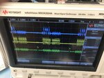
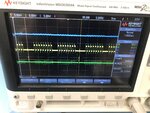
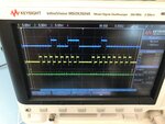
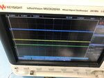
I try to control MCP41100 with SMT32F767. I enabled the SPI4 in transmit only master mode in CubeMX. Then I write a code in Keil IDE like in the below. I got 212.5mV output from wiper even I set to different values of Bias_Data_2 variables. Where do I make a mistake of control this POT?

Thank you,

Code in Keil:

Code:
uint8_t Data_Bias[1];
uint16_t Bias_Data_2;
uint8_t Bias_Write = 0x13;
uint16_t Bias_Buf;
...

while (1)
{
Bias_Data_2 = 255;
            HAL_GPIO_WritePin(BIAS_CS_GPIO_Port, BIAS_CS_Pin, GPIO_PIN_RESET);
            Bias_Buf = Bias_Write<<8 | Bias_Data_2;
            HAL_SPI_Transmit(&hspi4,(uint8_t*)&Bias_Buf,2,100);
            HAL_GPIO_WritePin(BIAS_CS_GPIO_Port, BIAS_CS_Pin, GPIO_PIN_SET);
            }


CubeMX Settings:

Code:
static void MX_SPI4_Init(void)
{

  /* USER CODE BEGIN SPI4_Init 0 */

  /* USER CODE END SPI4_Init 0 */

  /* USER CODE BEGIN SPI4_Init 1 */

  /* USER CODE END SPI4_Init 1 */
  /* SPI4 parameter configuration*/
  hspi4.Instance = SPI4;
  hspi4.Init.Mode = SPI_MODE_MASTER;
  hspi4.Init.Direction = SPI_DIRECTION_2LINES;
  hspi4.Init.DataSize = SPI_DATASIZE_16BIT;
  hspi4.Init.CLKPolarity = SPI_POLARITY_LOW;
  hspi4.Init.CLKPhase = SPI_PHASE_1EDGE;
  hspi4.Init.NSS = SPI_NSS_SOFT;
  hspi4.Init.BaudRatePrescaler = SPI_BAUDRATEPRESCALER_16;
  hspi4.Init.FirstBit = SPI_FIRSTBIT_MSB;
  hspi4.Init.TIMode = SPI_TIMODE_DISABLE;
  hspi4.Init.CRCCalculation = SPI_CRCCALCULATION_DISABLE;
  hspi4.Init.CRCPolynomial = 7;
  hspi4.Init.CRCLength = SPI_CRC_LENGTH_DATASIZE;
  hspi4.Init.NSSPMode = SPI_NSS_PULSE_ENABLE;
  if (HAL_SPI_Init(&hspi4) != HAL_OK)
  {
    Error_Handler();
  }
  /* USER CODE BEGIN SPI4_Init 2 */

  /* USER CODE END SPI4_Init 2 */

}
 

Hi,

one can not predict a wiper voltage without knowing what voltage is on PA and PB.

you are doing measurement results on a real circuit...but don´t show a schematic nor a photo.
So we are not able to verify anything regarding your measurement.

Klaus
 

Hi,

I assume "hspi4.Init.CLKPhase = SPI_PHASE_1EDGE;" sets the spi clock phase to 1. As the MCP4100 clocks the data in (SI pin) on a rising edge (DS page 12), you should use clock phase 0 in combination with your chosen clock polarity of 0 ("hspi4.Init.CLKPolarity = SPI_POLARITY_LOW;"). Doing so you are providing a stable voltage level when the clock signal changes from low to high, see [1].

Further I agree with @KlausST, as it is not clear how you are got your voltage levels.

[1] https://en.wikipedia.org/wiki/Serial_Peripheral_Interface#/media/File:SPI_timing_diagram2.svg

BR
 

Hi @KlausST and @stenzer,

Thank you for your comments!

I have attached my design as a block diagram.

DIG POT.png


In the CubeMX setting, the Clock phase set as either 1 Edge or 2 Edge. So, for low clock phase settings, I set it 1 edge. Is it true?

Thank you,
 

Hi,

What´s the STM supply voltage?
If 3.3V then:
* why the MCP is supplied with 5V ... this may cause V_IH violation on the MCP...

KLaus
 

I fixed the supply voltage as 3.3V for MCP41100. But I measure 3.28V from the PW0 pin whenever I change the Bias_Data_2 variable.
 

Hi,

we can´t see pin configuration, especially SPI including CS

Do you have a scope?

Klaus
 

Hi,

I have attached the photo shot of the oscilloscope. The green line is CS; yellow line is SCK; blue line is data.

Thank you,
 

Attachments

  • IMG_7856.jpg
    IMG_7856.jpg
    2 MB · Views: 185

Hi,

Your SPI clock is close to the maximum value.
There is no need for it. Especially your signals look as if you had no clean GND plane and maybe even lenghty wiring.
Reduce it to be below 1MHz. With bad/lenghty wiring you may reduce it more.

Use SPI in standard 8 bit mode. Transmit two bytes and get 16 bis in total.
Set CS=LOW just before transmitting data...and HIGH after ...
Use 10ms delay before you repeat.

Then do another scope picture that shows just from CS= low to CS=high. (To show the timing details)

Klaus
 

Thank you @KlausST !

I changed the clock rate to 843.75kBit/s by updating the prescaler to 128.

I set the data size in 8-bit mode.

Code:
Bias_Data_2=30;
HAL_GPIO_WritePin(BIAS_CS_GPIO_Port, BIAS_CS_Pin, GPIO_PIN_RESET); //CS is LOW
Bias_Buf = Bias_Write<<8 | Bias_Data_2;
HAL_SPI_Transmit(&hspi4,(uint8_t*)&Bias_Buf,2,100);
//HAL_Delay(10);
HAL_GPIO_WritePin(BIAS_CS_GPIO_Port, BIAS_CS_Pin, GPIO_PIN_SET); //CS is HIGH

When I enable the delay code, I lose CS, and SCK signals, so I disabled it. I measured 1.65V from PW0 everytime. Bias_data_2 values changes are not affecting the the POT.
 

Attachments

  • IMG_7857.jpg
    IMG_7857.jpg
    1.9 MB · Views: 165

Some embedded compilers delay promoting values to the next larger size until the last minute. Therefore 'Bias_Write<<8' (where Bias_Write is uint8_t in the first post) may be resulting in an 8-bit value of zero. Try casting the Bias_Write to uint16_t before the shift.
Also, if you intend to send the 'write' byte before the 'data' byte, then put the 'write' byte in the lower byte of 'Bias_Buf' and the 'data' in the upper byte (i.e. the 'data' value is the one that should be shifted).
However, looking at the HAL user manual, the HAL_SPI_Transmit function call would seem to be right and should be sending the (decimal)30 in the MOSI line.
The waveforms look better than they previous image but you are still having a lot of noise and overshoot (have you compensated the probes on the scope?).
Susan
 

Hi,

Please like in post#3.
...
First CS = LOW,
then delay
...
And show your variables delaration
Use an array of bytes
Byte0 = 0x13
Byte1 = 0x40

Klaus
 

Thank @KlausST and @Aussie Susan !

I updated the based on your suggestions.

Code:
int main (void)
{
/* USER CODE BEGIN 2 */
    HAL_GPIO_WritePin(BIAS_CS_GPIO_Port, BIAS_CS_Pin, GPIO_PIN_RESET);
    HAL_Delay(10);
  /* USER CODE END 2 */
    
  /* Infinite loop */
  /* USER CODE BEGIN WHILE */
  while (1)
  {
    /* USER CODE END WHILE */

    /* USER CODE BEGIN 3 */
            
            uint8_t Bias_Buf[2];
            Bias_Buf[0]=0x13;
            Bias_Buf[1]=0x40;
            HAL_SPI_Transmit(&hspi4,(uint8_t*)&Bias_Buf,2,100);
            HAL_GPIO_WritePin(BIAS_CS_GPIO_Port, BIAS_CS_Pin, GPIO_PIN_SET);
            
  }
  }

But when I run this code, CS is high every time. The measurement from PW0 is the same 1.65V.
 

The CS line will be high all the time because you only ever set it high within the main loop.
Also you have not put in the delay within the main loop as suggested.
Regardless of the CS pin (which you control), are you getting the correct SCK and MOSI values being sent?
I don't mean to sound harsh but please understand the code that you write - don't just randomly copy and paste code that has been suggested. If you were to step through your code yourself, you would see why the CS is always high.
Susan
 

Hi,

There is a typo in my post#12.

--> I wrote "post#3" but it should be "post#9".

Sorry for the confusion. Try this.

Code:
Code:
int main (void)
{
    uint8_t Bias_Buf[2];
    Bias_Buf[0]=0x13;
    Bias_Buf[1]=0x40;
  while (1)
  {
            HAL_GPIO_WritePin(BIAS_CS_GPIO_Port, BIAS_CS_Pin, GPIO_PIN_RESET);
            HAL_SPI_Transmit(&hspi4, &Bias_Buf, 2, 100);
            HAL_GPIO_WritePin(BIAS_CS_GPIO_Port, BIAS_CS_Pin, GPIO_PIN_SET);
            HAL_Delay(10);
  }
  }
Klaus
 
Last edited:
Thank you @KlausST and @Aussie Susan !

Actually, when the delay is active, the SCLK and DATA are disappeared, and CS is high. I have attached the without delay (straight lines) and with delayed versions of the signal outputs.
--- Updated ---

Appreciated with your support @KlausST @Aussie Susan @stenzer !

When I declare uint8_t Bias_Buf[2]; as a global variable, it worked. I measured 0.814 V when I set Bias_Buf[1]=0x40. Then I changed the Bias_Buf[1] as 0x20, I measured the half 0.407V.

Thank you very much especially @KlausST !
 

Attachments

  • IMG_7859.jpg
    IMG_7859.jpg
    1.7 MB · Views: 162
  • IMG_7858_1.jpg
    IMG_7858_1.jpg
    1.6 MB · Views: 161
Last edited:

Status
Not open for further replies.

Similar threads

Part and Inventory Search

Welcome to EDABoard.com

Sponsor

Back
Top