Continue to Site

Welcome to EDAboard.com

Welcome to our site! EDAboard.com is an international Electronics Discussion Forum focused on EDA software, circuits, schematics, books, theory, papers, asic, pld, 8051, DSP, Network, RF, Analog Design, PCB, Service Manuals... and a whole lot more! To participate you need to register. Registration is free. Click here to register now.

SPI Compatible ADC how to configure in Stm32?

Status
Not open for further replies.

MD18

Junior Member level 3
Joined
Dec 9, 2021
Messages
29
Helped
0
Reputation
0
Reaction score
0
Trophy points
1
Activity points
166
Hello,

I have to interface the ADS7046 12-Bit, 3-MSPS, Single-Ended Input, Small-Size, Low-Power SAR ADC. Spi compatible ADC 12 bit resolution and MSPS.
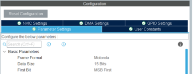
1.How to set its data size in spi configuration?
**broken link removed** datasheet they did not give the clock polarity which then I have to set?
SPI_ADC


2.Its maximum clock is 3MHz how to set ? I have to set less than 3Mhz clock to spi.
3.CS pin is GPIO is set ,in that I have to also manage the clock of GPIO?
4.First two bits is getting zero after that 12 bit is sampled after it get two zero. Then I have shifting the data to remove. the zeros.


Hi,

it´s hard to answer without knowing
* exact STM32 type
* IDE / compiler
* whether you use Stm32Cube
...

Why don´t you use the STM32 buuilt in ADC?

Klaus
 

I am using stm32h745ii stm32 controller.
I am using stm32cube ide and I have to configure the spi configuration in the cubemx.
In datasheet they mention that on falling edge of cs pin its start conversion they did not mentioned the Mode of spi and In one data I get the 15 data, so how I decided the data size 8 or 16?
SPi.PNG
 

Hi,

your ADC: 12 bit, 3MS/s
STM internal ADC: 12 bit 3MS/s
--> I don´t see the benefit.

*****

1) SPI is multiples of 8 bit. So if you want to transmit 16 bit, you usually just send 2 x 8bits.
But I think the STM32 allowes you to use 16 bit access. This may be a benefit with using your ADCm but at the same time it may cause incompatibilities with 8 bit devices on the bus.

2) Fig 37 does not give timing relations. You need to check Fig1 and Fig2.
see: https://en.wikipedia.org/wiki/Serial_Peripheral_Interface
It should be Mode0 compatible.

3) Two differnet things:
* ADC SPI SCK frequency is 60MHz max --> set less than 60MHz STM32 SPI clock frequency / baud rate
* ADC data rate / sampling rate is 3MHz max.... this is the /CS frequency. Start a conversion ( falling edge of CS) with a frequency of less than 3MHz.

4) STM32 usually is able to generate CS automatically.
Alternatively you may use a GPIO. For a constant sampling rate:
* use a pulse generating mode (PWM hardware) and synchronize SPI transfer with it.
* or use a counter interrupt

5) 16 bits are transferred. 12 bits ADC data.
You may sihf the data for right or left alignment.
But you may also use it as it is and include this in the math ... for example when multiplying the ADC value to get volts.

Klaus
 

Hello!

1) SPI is multiples of 8 bit. So if you want to transmit 16 bit, you usually just send 2 x 8bits.

Usually yes, but apparently STM32 allows to select different (and odd) bit numbers. At least STM32CubeMX
allows it, any value between 4 and 16 included. I have never tried, not sure what the hardware does if you set
for instance 5 bit data. I will check next time I use a ST board.

Dora.
 

Hi,

your ADC: 12 bit, 3MS/s
STM internal ADC: 12 bit 3MS/s
--> I don´t see the benefit.

*****

1) SPI is multiples of 8 bit. So if you want to transmit 16 bit, you usually just send 2 x 8bits.
But I think the STM32 allowes you to use 16 bit access. This may be a benefit with using your ADCm but at the same time it may cause incompatibilities with 8 bit devices on the bus.

2) Fig 37 does not give timing relations. You need to check Fig1 and Fig2.
see: https://en.wikipedia.org/wiki/Serial_Peripheral_Interface
It should be Mode0 compatible.

3) Two differnet things:
* ADC SPI SCK frequency is 60MHz max --> set less than 60MHz STM32 SPI clock frequency / baud rate
* ADC data rate / sampling rate is 3MHz max.... this is the /CS frequency. Start a conversion ( falling edge of CS) with a frequency of less than 3MHz.

4) STM32 usually is able to generate CS automatically.
Alternatively you may use a GPIO. For a constant sampling rate:
* use a pulse generating mode (PWM hardware) and synchronize SPI transfer with it.
* or use a counter interrupt

5) 16 bits are transferred. 12 bits ADC data.
You may sihf the data for right or left alignment.
But you may also use it as it is and include this in the math ... for example when multiplying the ADC value to get volts.

Klaus
1.In data.png image we can set the 16bit data.So instead of 8 bit can I set it 16 bit?
3.Data In and out rate speed is 60Mhz max which can set by the SPI,but for ADC sampling how and where I have to set frequncy means In stm clock dig in cubemx there is no way to set frequncy of GPIO then how i can set the 3MHz.
4.How can I decide how much frequncy of SPI I can set for this communication?
 

Attachments

  • data.PNG
    data.PNG
    19.6 KB · Views: 97

Hi,

all questions of your post#6 are already answered in the above posts#4 and #5.

What exact information do you miss?

Klaus
 

I am get how much clock of spi I have to set?
 

Hi,

I´m confused.
You mean minimum baud rate? or maximum or exact?

Klaus
 

Hi,

I´m confused.
You mean minimum baud rate? or maximum or exact?

Klaus
Hello,

The SPI frequency max is 60MHZ.How much SPI frequency I need to give the SPI clock so My communication is get done. Because in Cubemx I can only set my SPI frequency. I cant set the GPIO (CS) frequncy below 3MHz.
The Fsample is 3MHZ max and SPI is 60Mhz so I get confused .
 

M
Hello,

The SPI frequency max is 60MHZ.How much SPI frequency I need to give the SPI clock so My communication is get done. Because in Cubemx I can only set my SPI frequency. I cant set the GPIO (CS) frequncy below 3MHz.
The Fsample is 3MHZ max and SPI is 60Mhz so I get confused .
Exact what spi clock / baudrate I have to set for making proper communication
 

Hi,

* maximum is given
* no "exact" needed.
* "minium" depends on sampling rate ... and the timing given in the ADC datasheet.

See the diagram of your post#1.
the sampling rate is given by CS signal... falling edge to falling edge is the timing for one sample.
Just as example:
You want a sampling rate of 100kS/s, this means 10us form CS_falling to CS_falling.

.. during this 10us you need
* to ensure the necessary timing until SCK starts
* transmit 16 bits (16 SCK cycles)
* ensure the necessary timing until CS_rising
* ensure timing for CS_HIGH
(so basically the time for transmitting 16 bits plus some overhead)

So it depends a lot on the requirements of your application.

One can say:
* the higher the SPI baud rate, the more relaxed is the other ADC timing, and the higher the maximum possible sampling rate.
* but also: the higher the SPI baud rate the more problems with bit timing, PCB layout, trace length, signal ringing...

Klaus
 
Status
Not open for further replies.

Similar threads

Part and Inventory Search

Welcome to EDABoard.com

Sponsor

Back
Top