Continue to Site

Welcome to EDAboard.com

Welcome to our site! EDAboard.com is an international Electronics Discussion Forum focused on EDA software, circuits, schematics, books, theory, papers, asic, pld, 8051, DSP, Network, RF, Analog Design, PCB, Service Manuals... and a whole lot more! To participate you need to register. Registration is free. Click here to register now.

Speed Control of DC Motor using PIC16F877?

Status
Not open for further replies.
Re: photo transistor pic16f

hi mr. tahmid..
i was reading through your code. but i am having a question. why u having a compare mode at ccp2? and do u have c file for this asm code? im not good at asm...
quick reply would be appriciated....

thank you
 
Hi,
Yes, I have a mikroC program. It's for 16F877A, follow the same circuit diagram.
Code:
unsigned int ADR;

void main() {
     TRISA = 0xFF;
     PORTC = 0;
     TRISC = 0;
     PORTC = 0;

     PWM1_Init(5000);
     PWM1_Set_Duty(128);
     PWM1_Start();

     while (1){
           ADR = ADC_Read(0);
           if (ADR > 0)
              ADR = (ADR >> 2) - 1;
           if (ADR < 5)
              ADR = 5;
           if (ADR > 250)
              ADR = 250;
           PWM1_Set_Duty(ADR);
     }
}

Hope this helps.
Tahmid.
 

Re: photo transistor pic16f

hi tahmid..
thankx for the reply... i have also have almost the same code using ccp1con resister.. and u used the pwm library from mikroC.. i also want to know on ur asm code why did u have a compare mode on ccp2 pin??
by the way im also from bangladesh currently living in london... i have completed my BEng(H) in EEE and currently working on a project for a model electronic car...
nice to meet u...

Omar
 

Hi,
The CCP2 module is working in compare mode special trigger that triggers an analogue to digital conversion after the flag is raised. The compare mode period is set for 1ms. So every 1ms, an analogue to digital conversion takes place. This could also be done with a delay or something, but at that time, since I was learning on how to use the CCP modules, I used compare mode instead.

Hope this helps.
Tahmid.
 

Thanks for the reply..
i am sending u a code with proteus design file..plz check that..the problem with the simulation is it says "ADC conversion started befor wait time expired" but it should not say that as i have a 10ms delay using delay_ms function.. plus on the proteus simulation the motor runs faster when adc value=0767 but slower when adc value=0777. also the motor flickers when adc value is below 100..is it any problem with the code? i could not test it on the development board as i don have motor..
im using p16f877 at 8 MHz clock and mikroC..plz replay
 

Attachments

  • New WinRAR archive.rar
    2.5 KB · Views: 88

Hi,
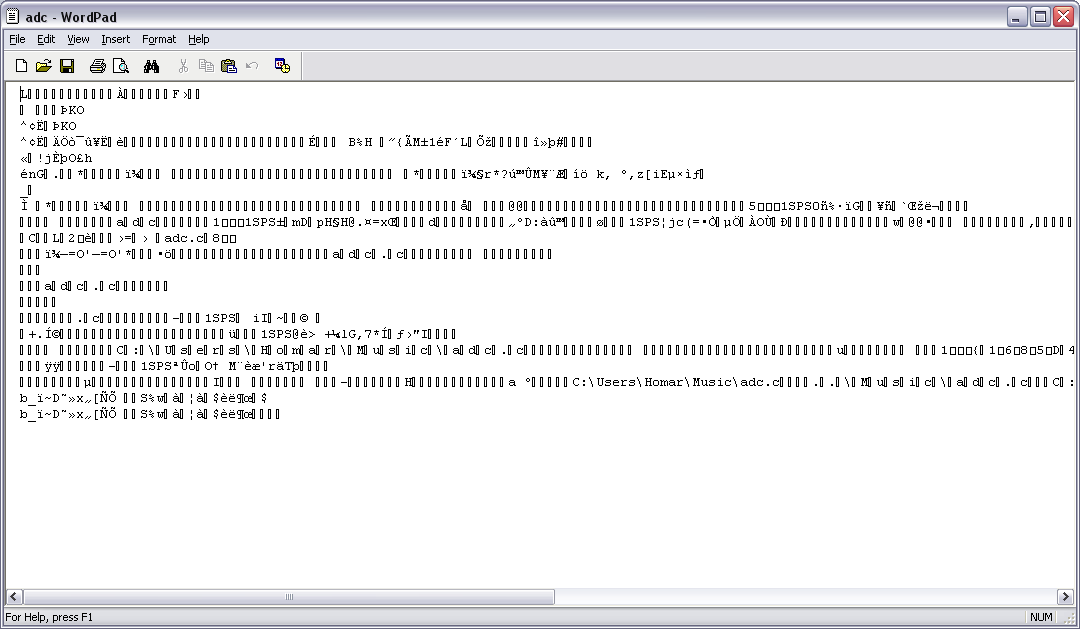
Can you please upload the files again and also attach your Proteus file? The files you uploaded look like garbage.
75_1293510649.png


I think the problem is clock setting in Proteus. In Proteus, double click the 16F877. In the text box "Processor Clock Frequency" enter 8MHz. I think you did not set that properly, that's why the error is there.

Hope this helps.
Tahmid.
 

you can use PWM output of the pic and control the width of the pulses such that if the width of the pulses is large then the dc average is high and the motor will speed up
and if the width of the pulse is small compared to it's period then the dc average is small and the motor will slowed down
 

Thanks guys...
i have managed to solve the problem..i had to reconfigure the duty cycle on CCPR1L resister and the problem is solved..
thanks anyway
 

Status
Not open for further replies.

Part and Inventory Search

Welcome to EDABoard.com

Sponsor

Back
Top