Continue to Site

Welcome to EDAboard.com

Welcome to our site! EDAboard.com is an international Electronics Discussion Forum focused on EDA software, circuits, schematics, books, theory, papers, asic, pld, 8051, DSP, Network, RF, Analog Design, PCB, Service Manuals... and a whole lot more! To participate you need to register. Registration is free. Click here to register now.

Spatial Scattering Parameters of Volume Loss Density in HFSS

Status
Not open for further replies.

dopplerjeff5000

Newbie level 5
Joined
Dec 11, 2012
Messages
9
Helped
2
Reputation
4
Reaction score
1
Trophy points
1,283
Activity points
1,343
Hi!

Does anyone know how to plot the scattering parameters or volume loss density over only a certain part of the simulation? I'd like to see in a complex simulation the areas where I'm losing the most power, and I'd like to be able to plot a frequency sweep of one section of the model versus another.

Thanks!
 

Hi dopplerjeff5000,

You'd have to do this manually, i.e. without using wave ports. What you need to do is insert surfaces over the areas that you are interested in, then use the fields calculator to integrate the Poynting vector over those surfaces. From the input and output surfaces as "ports", you can calculate the scattering or loss.

Good Luck
 
Thanks for the prompt and thorough reply. I will try what you suggest!
 

Hi dopplerjeff5000,

You'd have to do this manually, i.e. without using wave ports. What you need to do is insert surfaces over the areas that you are interested in, then use the fields calculator to integrate the Poynting vector over those surfaces. From the input and output surfaces as "ports", you can calculate the scattering or loss.

Good Luck

I have a similar simulation going on (plane wave excitaiton, and want to get the incident power going into the simulation and scattered off). I was trying to integrate the poynting vector at a boundary between a Pml and airbox where I have a plane wave excitation, but it doesn't seem to work. Does anyone have any tips for how this is done in HFSS. I can't get this to work in the field calculator.... It keeps saying "the stack contents are incompatible with the current operation". Although I can easily plot the poynting vector in HFSS at this boundary.
 

Hi PlanarMetamaterials,

Thanks for your quick reply! I think I managed to get it to solve (sort of), but now it is giving an answer that doesn't seem to make sense.

I am copying "Vector_RealPoynting" to the stack, then the interface in the geometry between the pml and airbox, then selecting "scalar z". Then, I am integrating and clicking "Eval". The result is a negative number -1.659x10⁻¹³!

When I plot the poynting vector in the model I can see the value is right around the expected value of 0.00133 W/m2. Correct me if I am wrong, but if the size of the interface is 0.005mX0.025m=.000125m2, then the power should be .000125m2 X .00133W/m2? See attached picture

- - - Updated - - -

Also, I should mention that I tried to do it with the "Normal" component selected as advised by the attached document, but it gave me the same answer (I guess that's expected to be the same). Seems weird that it's negative.... Is it because I did this at the pml/air boundary?

I am a chemist so I could easily be missing something! :-|
 

Attachments

  • ponyting vector plot at pml interface.jpg
    ponyting vector plot at pml interface.jpg
    179.9 KB · Views: 141
  • cookbook.doc
    1.3 MB · Views: 86

Hi eztucker,

That should give you the value at a specific point. You need to integrate the power over a sheet. Once you have the surface for geometry, select normal (to get power flowing through the surface), and then select integrate.
 
Hi eztucker,

That should give you the value at a specific point. You need to integrate the power over a sheet. Once you have the surface for geometry, select normal (to get power flowing through the surface), and then select integrate.

PlanarMetamaterials,

Thanks for your help, really appreciate it! I just made a stupid mistake.....:oops: 
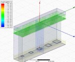
The geometry is in microns so it should be 1.25x10⁻¹⁰m2 and a few rounding errors skew it a little, but it now gives the expected results. I guess it's negative because the wave is traveling down (-z direction). Cheers.

ezt
 

Status
Not open for further replies.

Part and Inventory Search

Welcome to EDABoard.com

Sponsor

Back
Top