Continue to Site

Welcome to EDAboard.com

Welcome to our site! EDAboard.com is an international Electronics Discussion Forum focused on EDA software, circuits, schematics, books, theory, papers, asic, pld, 8051, DSP, Network, RF, Analog Design, PCB, Service Manuals... and a whole lot more! To participate you need to register. Registration is free. Click here to register now.

Spartan 3e FPGA VGA problem

Status
Not open for further replies.

hitx

Member level 2
Joined
Mar 16, 2007
Messages
49
Helped
1
Reputation
2
Reaction score
1
Trophy points
1,288
Activity points
1,723
Hi dear friends,

I have a serious problem about Spartan 3E, x3c100K cp132 family. I have to control a monitor to display various color using VGA port. This might be easy, but I am beginner for VHDL. However, I have not managed yet. And I am becoming much more crazy :twisted: I need a VGA controller in VHDL. I used lots of codes from internet, but I saw only black screen on monitor. :grin: Probebly I missed something in codes. I really need help.

I found a code in VHDL for VGA controller below. This codes never gives any error. But I did not see anything on monitor. What should I do? Please help me.

Thanks.


Code VHDL - [expand]
1
2
3
4
5
6
7
8
9
10
11
12
13
14
15
16
17
18
19
20
21
22
23
24
25
26
27
28
29
30
31
32
33
34
35
36
37
38
39
40
41
42
43
44
45
46
47
48
49
50
51
52
53
54
55
56
57
58
59
60
61
62
63
64
65
66
67
68
69
70
71
72
73
74
75
76
77
78
79
80
81
82
83
84
85
86
87
88
89
90
91
92
93
94
95
96
97
98
99
100
101
102
103
104
105
106
107
library IEEE;
use IEEE.STD_LOGIC_1164.ALL;
use IEEE.STD_LOGIC_ARITH.ALL;
use IEEE.STD_LOGIC_UNSIGNED.ALL;
 
entity vgatest is
  port(clk50_in  : in std_logic;
       red_out   : out std_logic;
       green_out : out std_logic;
       blue_out  : out std_logic;
       hs_out    : out std_logic;
       vs_out    : out std_logic);
end vgatest;
 
architecture behavioral of vgatest is
 
signal clk25              : std_logic;
signal hcounter : integer range 0 to 800;
signal vcounter   : integer range 0 to 521;
signal color: std_logic_vector(2 downto 0);
begin
 
-- generate a 25Mhz clock
process (clk50_in)
begin
  if clk50_in'event and clk50_in='1' then
    clk25 <= not clk25;
  end if;
end process;
 
-- change color every one second
p1: process (clk25)
    variable cnt: integer;
begin
    if clk25'event and clk25='1' then
        cnt := cnt + 1;
        if cnt = 25000000 then
            color <= color + "001";
            cnt := 0;
        end if;
    end if;
end process;
 
p2: process (clk25, hcounter, vcounter)
    variable x: integer range 0 to 639;
    variable y: integer range 0 to 479;
begin
    -- hcounter counts from 0 to 799
    -- vcounter counts from 0 to 520
    -- x coordinate: 0 - 639 (x = hcounter - 144, i.e., hcounter -Tpw-Tbp)
    -- y coordinate: 0 - 479 (y = vcounter - 31, i.e., vcounter-Tpw-Tbp)
    x := hcounter - 144;
    y := vcounter - 31;
    if clk25'event and clk25 = '1' then
        -- To draw a pixel in (x0, y0), simply test if the ray trace to it
        -- and set its color to any value between 1 to 7. The following example simply sets 
        -- the whole display area to a single-color wash, which is changed every one 
        -- second.  
        if x < 640 and y < 480 then
        red_out <= color(0);
        green_out <= color(1); 
        blue_out <= color(2);
        else
            -- if not traced, set it to "black" color
        red_out <= '0';
        green_out <= '0';
        blue_out <= '0';
        end if;
        -- Here is the timing for horizontal synchronization.
        -- (Refer to p. 24, Xilinx, Spartan-3 Starter Kit Board User Guide)
        -- Pulse width: Tpw = 96 cycles @ 25 MHz
        -- Back porch: Tbp = 48 cycles
        -- Display time: Tdisp = 640 cycles
        -- Front porch: Tfp = 16 cycles
        -- Sync pulse time (total cycles) Ts = 800 cycles
 
        if hcounter > 0 and hcounter < 97 then
        hs_out <= '0';
        else
        hs_out <= '1';
        end if;
        -- Here is the timing for vertical synchronization.
        -- (Refer to p. 24, Xilinx, Spartan-3 Starter Kit Board User Guide)
        -- Pulse width: Tpw = 1600 cycles (2 lines) @ 25 MHz
        -- Back porch: Tbp = 23200 cycles (29 lines)
        -- Display time: Tdisp = 38400 cycles (480 lines)
        -- Front porch: Tfp = 8000 cycles (10 lines)
        -- Sync pulse time (total cycles) Ts = 416800 cycles (521 lines)
        if vcounter > 0 and vcounter < 3 then
        vs_out <= '0';
        else
        vs_out <= '1';
        end if;
        -- horizontal counts from 0 to 799
        hcounter <= hcounter+1;
        if hcounter = 800 then
        vcounter <= vcounter+1;
        hcounter <= 0;
        end if;
        -- vertical counts from 0 to 519
        if vcounter = 521 then          
        vcounter <= 0;
        end if;
  end if;
end process;
 
end behavioral;


PLEASE USE CODE TAGS IN THE FUTURE
 
Last edited by a moderator:
Well, let's assume above code is correct.
Other than above code, you (should) have other code as well. By this I mean the code that instantiates above entity and 'connects' to the real hardware.
It is this code that, could, probably be the problem. For instance, above instantiation needs a 50 MHz clock. If you don't provide the correct clock speed, by means of the 'other' code, then the result will be no picture too because of incorrect timing.
So, don't only suspect above VGA code, but have a good look at the other code as well. And besides that, have you used a test-bench for above code and checked the timings/signals?
 

I have used a test bench for the codes and I guess that it seems true. However, there is something possible. I used LED monitor to control the screen , but should I use a CRT monitor? Do you think that this situation might be a reason?

Thanks Marcel
 

The LED, LCD, or CRT, monitor obviously must support the 'signals' you are generating.
Basically it should not matter what kind you are using, but it might be that the 'older' electronics (the 'analog'/'non-digitzing' electronics), might be more 'forgiving' when using signals that are not 'up to specs'.
 

Hi my friend,

I am trying to understand the situation. However, there is something not clear in my mind. Now, my VHDL codes based on 640 x 480 screen as a standard of VGA. However, the LED screen that will display the image, has a 1340 screen. So, do I have to change my vhdl codes to 1340 or it is unnecassary to change due to 1340 LED also supports ? I am realyy confused :

Thanks
 

If your LED/LCD supports such a 640x480 resolution (as it should), then it will either stretch/enlarge the signal or just use a smaller portion of the screen for it.
Basically, the LED/LCD will do it's own upscale/downscaling of the signal on the input. As long as you provide a supported resolution, with the appropriate timings of course, there should be no problem.
 

How did you set up your pin constraints, do you have the .ucf file? It appears the dev board you are using is configured for one bit per RGB channel.. is this correct for the type of board that you're using?

I noticed a few other odd things in your code but lets start with this.
 

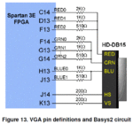
It appears hitx is using the following for his design:
Capture.GIF

This is the first board I came across that uses both a 100K 3E and the chipscale pkg and seems to be a common board used by a lot of "students".

If this is the correct board the FPGA output is a 3-bit value for each of the RG outputs and 2-bit value for the B outputs.
 

Thanks ads_ee, I think you're right.

Hitx, try this out, it should fix your problems. Obviously the current code you have isn't going to work because you need to expand the number of output bits for RGB. You also need a pin constraints file.. have you made one yet? I'm skeptical that you have.

When you're done making it, it should look like this: :smile:
Code:
NET "clk50_in"     loc = "B8"  | IOSTANDARD = LVTTL | SLEW = SLOW | DRIVE = 8 ;
NET "red_out<0>"   loc = "C14" | IOSTANDARD = LVTTL | SLEW = SLOW | DRIVE = 8 ;
NET "red_out<1>"   loc = "D13" | IOSTANDARD = LVTTL | SLEW = SLOW | DRIVE = 8 ;
NET "red_out<2>"   loc = "F13" | IOSTANDARD = LVTTL | SLEW = SLOW | DRIVE = 8 ;
NET "green_out<0>" loc = "F14" | IOSTANDARD = LVTTL | SLEW = SLOW | DRIVE = 8 ;
NET "green_out<1>" loc = "G13" | IOSTANDARD = LVTTL | SLEW = SLOW | DRIVE = 8 ;
NET "green_out<2>" loc = "G14" | IOSTANDARD = LVTTL | SLEW = SLOW | DRIVE = 8 ;
NET "blue_out<0>"  loc = "H13" | IOSTANDARD = LVTTL | SLEW = SLOW | DRIVE = 8 ;
NET "blue_out<1>"  loc = "J13" | IOSTANDARD = LVTTL | SLEW = SLOW | DRIVE = 8 ;
NET "hs_out"       loc = "J14" | IOSTANDARD = LVTTL | SLEW = SLOW | DRIVE = 8 ;
NET "vs_out"       loc = "K13" | IOSTANDARD = LVTTL | SLEW = SLOW | DRIVE = 8 ;

Here are the modifications to your code to get it to work. These changes are quite simple.. and somewhat hard to miss. Also, it looks like the timing for your vertical sync is off a few counts. It's likely most monitors will sync up properly despite this, however you may want to change it so you look like you know what you're doing.


Code VHDL - [expand]
1
2
3
4
5
6
7
8
9
10
11
12
13
14
15
16
17
18
19
20
21
22
23
24
25
26
27
28
29
30
31
32
33
34
35
36
37
38
39
entity vgatest is
  port(clk50_in  : in std_logic;
       red_out   : out std_logic_vector(2 downto 0); -- modified
       green_out : out std_logic_vector(2 downto 0); -- modified
       blue_out  : out std_logic_vector(1 downto 0); -- modified
       hs_out    : out std_logic;
       vs_out    : out std_logic);
end vgatest;
 
architecture behavioral of vgatest is
 
signal clk25    : std_logic;
signal hcounter : integer range 0 to 800;
signal vcounter   : integer range 0 to 524; -- modified from 521
signal color: std_logic_vector(2 downto 0);
begin
 
...
 
        -- To draw a pixel in (x0, y0), simply test if the ray trace to it
        -- and set its color to any value between 1 to 7. The following example simply sets 
        -- the whole display area to a single-color wash, which is changed every one 
        -- second.  
        if x < 640 and y < 480 then
        red_out <= color(0) & color(0) & color(0); -- modified
        green_out <= color(1) & color(1) & color(1); -- modified 
        blue_out <= color(2) & color(2); -- modified
        else
 
...
 
        -- vertical counts from 0 to 519
        if vcounter = 524 then  -- modified from 521        
        vcounter <= 0;
        end if;
  end if;
end process;
 
end behavioral;


Lastly, here are the specs for video 640x480 @ 60Hz
http://tinyvga.com/vga-timing/640x480@60Hz
 

Hi dear all friends,

Thanks a lot for trying to help me. I have solved the problem by using CRT monitor instead of LED screen. Now I can control RGB signals on screen. By the way, I have never changed any values in codes. I really surprised for the solution, however, I think it is not logical, why LED screen not diplays any RGB ?? In my opinion, LED must also supports VGA signals, is not that ??? ANYWAY, I am really happy for the current situation. Thanks again.

Now I have to store data in internal memory, does anybody have an idea for this ???? :):)

Best Wishes
Hitx.
 

Status
Not open for further replies.

Similar threads

Part and Inventory Search

Welcome to EDABoard.com

Sponsor

Back
Top