wcgan
Member level 2
Hi all,
I am fresh to PIC controller, i hv some basic microcontroller question need you help..
Question 1:Memory Size:
For 8051, datasheet written
- 128 x 8-bit Internal RAM
is that means 1 memory location can store 8-bits data. total hv 128 memory location, so the total memory RAM size is
128 x 8 bits = 1024 bits
128 x 1 byte = 128bytes
is that the same calcucaltion theory can apply to PIC controller?
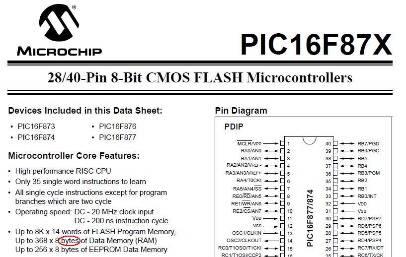
from PIC16F876 datasheet,
Up to 8K x 14 words of FLASH Program Memory,
Up to 368 x 8 bytes of Data Memory (RAM)
Up to 256 x 8 bytes of EEPROM Data Memory
is that means 1 memory location can store 8-bytes data, total hv 368 memory location, so the total memory size is
#cal1
368 x 8 x 8 bits = 23552 bits
368 x 8 bytes = 2944 bytes
OR
#cal2
368 x 8 bits = 2944 bits
368 x 1 byte = 368 bytes
which calculation is correct? if cal2 is correct, y the unit display on datasheet is 'bytes' NOT 'bits'?
Up to 368 x 8 bits of Data Memory (RAM)
is that the standard display way for the microcontroller?
Up to 8K x 14 words of FLASH Program Memory
1 words = 4 bytes
8k x 14 words = 8k (memory location) x (14 x 4) = 448000 bytes?
Question 2:14-bits op-code vs. 8-bits op-code:
what means of 14-bits op-code? what r the different between 8 bits op-code?
is that means they can do more task on one command?
example:
A = 0x05 + 0x09;
in 8051,(8-bits op-code)
ADD A,#05H
ADD A,#09H
in PIC,(16-bits op-code)
ADD A,#05H,#09H
16-bits op-code can done the job on one 'ADD' command?
Thanks for your help.
I am fresh to PIC controller, i hv some basic microcontroller question need you help..
Question 1:Memory Size:
For 8051, datasheet written
- 128 x 8-bit Internal RAM
is that means 1 memory location can store 8-bits data. total hv 128 memory location, so the total memory RAM size is
128 x 8 bits = 1024 bits
128 x 1 byte = 128bytes
is that the same calcucaltion theory can apply to PIC controller?
from PIC16F876 datasheet,
Up to 8K x 14 words of FLASH Program Memory,
Up to 368 x 8 bytes of Data Memory (RAM)
Up to 256 x 8 bytes of EEPROM Data Memory
is that means 1 memory location can store 8-bytes data, total hv 368 memory location, so the total memory size is
#cal1
368 x 8 x 8 bits = 23552 bits
368 x 8 bytes = 2944 bytes
OR
#cal2
368 x 8 bits = 2944 bits
368 x 1 byte = 368 bytes
which calculation is correct? if cal2 is correct, y the unit display on datasheet is 'bytes' NOT 'bits'?
Up to 368 x 8 bits of Data Memory (RAM)
is that the standard display way for the microcontroller?
Up to 8K x 14 words of FLASH Program Memory
1 words = 4 bytes
8k x 14 words = 8k (memory location) x (14 x 4) = 448000 bytes?
Question 2:14-bits op-code vs. 8-bits op-code:
what means of 14-bits op-code? what r the different between 8 bits op-code?
is that means they can do more task on one command?
example:
A = 0x05 + 0x09;
in 8051,(8-bits op-code)
ADD A,#05H
ADD A,#09H
in PIC,(16-bits op-code)
ADD A,#05H,#09H
16-bits op-code can done the job on one 'ADD' command?
Thanks for your help.