Continue to Site

Welcome to EDAboard.com

Welcome to our site! EDAboard.com is an international Electronics Discussion Forum focused on EDA software, circuits, schematics, books, theory, papers, asic, pld, 8051, DSP, Network, RF, Analog Design, PCB, Service Manuals... and a whole lot more! To participate you need to register. Registration is free. Click here to register now.

[SOLVED] Solenoid Driver Using PWM, Current Source.

Status
Not open for further replies.

dhruv_electro

Advanced Member level 4
Joined
Dec 17, 2010
Messages
118
Helped
9
Reputation
18
Reaction score
8
Trophy points
1,298
Location
India
Activity points
2,378
Hi,

Our basic need is to open solenoid(s) 0 to 100% using MCU. Functional description of hardware is listed below.

1. Total no of solenoid to operate is 12.
2. Current source can very from 0-500mA (please see attchment).

Functional Block.jpg

3. Current sensing is needed only for Over and Under current protection and error generation.
4. Available supply rails are 24VDC, 12VDC and 5VDC.
5. Any time One or Two Solenoid is functioning, rest will be in OFF (complete closed) mode.


The attachment contains two PWM, 1 for Coarse tuning and 1 for Fine Tuning. This is done because there are two type of solenoid, when we tested using controlled current source, 24VDC first one starts opening at 350mA and at 450mA it is fully opened. Other one starts at 200mA and Fully Opened at 350mA. We wanted to have control of 0-100% operation. So we decided to have a coarse tuning and a fine tuning PWM, fine tuning will take care for full 0-100% range, and coarse PWM provide basic current, Later we will use AND gate network to enable multiple solenoid. I think this method is Current Controlled. Basic query is for how solenoid should be driven for 0 to 100% operation, are we on right track? Or we are doing complex solution when there may be other options available?? like many top level members suggested in this post:

https://www.edaboard.com/threads/130480/

We don't know what to call but these may be voltage controlled options, Is it suit us? Here we needed to provide current feedback for Over and Under current errors.

We have done some digging if any other options available, so we have this special ICs from TI:

1. **broken link removed** (with Over current Under current and Thermal Protection / fault indication)
2. DRV103 (with Over current and Thermal Protection / fault indication)

Both are using a PWM Duty cycle control Input which can take Analog Voltage (DRV101 : 0.75-3.7V for 90%-10% and DRV103 :1.3V-3.9 10% to 90%) with that we can control Solenoid and pain will be lesser, But both are quite costlier, and DRV103 is not providing under current indication. Is it ok if we go for this kind of options? (Price of hardware is over budget if we are using it for 12 channels.) Or would you suggest other solutions for our need?

Thanks in advance.

- - - Updated - - -

Meanwhile we got the all different solenoids and measured the coil resistance:

1. 42 Ohms
2. 53 Ohms
3. 68 Ohms
 

If you consider a PWM driver like DRV10x , you can simply drive a transistor switch directly from MCU and get rid of the redundant D/A/D conversion.

DRV10x or a direct processor controlled PWM don't provide constant current control, there should be a current feedback.

I don't get the particular purpose of the coarse/fine control. There's however no accuracy and resolution specificication, so everything is rather vague.

You should consider that a proportional solenoid controller might take advange from a certain amount of current ripple respectively specifically tuned PWM frequency to overcome valve hysteresis.
 

Hi FvM,

Thank for you reply. We were expecting you.

I don't get the particular purpose of the coarse/fine control. There's however no accuracy and resolution specificication, so everything is rather vague.

Sorry for the confusion. It was just an idea to drive a solenoid, but after posting here we have searched the possibilities at many places and what we got that below concept could serve our purpose:

Functional Block.jpg


Please give your review on this.

If you consider a PWM driver like DRV10x , you can simply drive a transistor switch directly from MCU and get rid of the redundant D/A/D conversion.

DRV10x or a direct processor controlled PWM don't provide constant current control, there should be a current feedback.

Thanks for the point.

You should consider that a proportional solenoid controller might take advange from a certain amount of current ripple respectively specifically tuned PWM frequency to overcome valve hysteresis.

Would you mind to elaborate this please. ??

Meanwhile We will submit some schematic for your approval and the details like accuracy and resolution as you required.

Thanks again for taking interest.
 

I think the new topology can work well for the intended purpose. Resolution and accuracy will be mainly determined by PWM and ADC parameters. Proportional valves have often limited repeatability so a feedback of primary process value (e.g. flow or pressure) may be preferable.
 

This looks okay, in principle. An alternative method would be to use a DAC to provide a setpoint to an external analog feedback loop. That way the feedback is handled in hardware rather than software. Not inherently better, but some people prefer it that way.
 

Hi there,

First Thanks for replying and taking interest.

This looks okay, in principle. An alternative method would be to use a DAC to provide a setpoint to an external analog feedback loop. That way the feedback is handled in hardware rather than software. Not inherently better, but some people prefer it that way.

Thanks for the input, we will consider it in future process if and when needed.

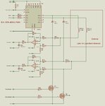
Meanwhile, application we are working on is Gear Transmission assembly ECU. In which Total No of Solenoid in hardware are 12-13 and No of Solenoid Operated at each Gear : 2-3. We have found one hardware for same Engine, from our local scarp distributor. Hardware is not working, may be short circuited by some water damage, but we are able to see the parts soldered in the path for the solenoid. Our only intention here is take idea that how they have driven the solenoid and how they have taken the feedback It contains following parts for the task.

Functional Block.jpg

From above attachments:

1. Digital logic for solenoid selection contains ICs like 74HC08 and 74HC241, this select solenoid(s) for current gear, i.e. PWM is passed to particular solenoid driver.
2. **broken link removed** : here we wanted some help, This is high side Mosfet+driver+Fault_detection_protection device. But this is not available with our local supply. Will you please suggest us the device to replace this? In any case if we go for BTS410F, still the query regarding How much PWM frequency we can use with this device?
3. Supply line on Pin 3 VBB of BTS410F is 24VDC.
4. Instead of using LM2902D, Can we use TLC272 for current sensing..?? Only reason is that TLC272 is available with us.

As MCU we have PSOC3 device form Cypress.

Resolution and accuracy will be mainly determined by PWM and ADC parameters.

Available resources for both PWM and ADC are 16bit.

Proportional valves have often limited repeatability so a feedback of primary process value (e.g. flow or pressure) may be preferable.
.

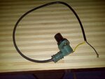
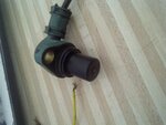
We do have one RPM sensor here, but still we are finding the data for that sensor:

IMG-20140103-00624.jpg

We will update the more data of RPM later and upload here after some tests.
 

Attachments

  • IMG-20140103-00627.jpg
    IMG-20140103-00627.jpg
    275.3 KB · Views: 154
Last edited:

Is there any technical reason to ground connected solenoids? Otherwise NMOS output transistors with ground referred shunt would be the most simple solution.

"Smart" power switches like BTS series are intentionally slow to reduce EMI, the switching dV/dt specification tells about it. PWM frequencies up to a few kHz should be feasible, you get relative large switching losses at higher frequencies. Other manufacturers are e.g. IRF and ST.
 

I still do not understand what you are attempting. You started of by saying 0 -100% , then talk about " analog Voltage (DRV101 : 0.75-3.7V for 90%-10% and DRV103 :1.3V-3.9 10% to 90%) ", which is not 0 -100%.
I would build an analogue solenoid driver, which will give a 0 -100% current from a 1 to 6V input. The current being switch selectable on the module, to suit the solenoid it is driving. An additional input could be a "switch off" signal, though it is not clear what the solenoid would do. The analogue side should be able easily to keep the current to +- .1% of the input voltage range. Also the analogue module can be tested as an individual and replaced as an individual.
The next common module will be the multiplexer/buffers/addressing chips and the D to As. This is so a digital value can be changed to analogue, with the digital value being buffered, so the analogue value remains constant until the next new current is addressed to any module. Here your spec. goes all vague, do you want to vary all the solenoids at different rates? test their current v linear movement? . ..
Just my thoughts
Frank
 

Hi there,

Sorry for late reply, we were busy with work.

Is there any technical reason to ground connected solenoids?

No. We have both the wire coming out from all solenoids so we can work with any topology as you suggest.

Otherwise NMOS output transistors with ground referred shunt would be the most simple solution.

R u suggesting like: High side current sensing with low side switch.?? like this?

Functional Block.jpg

In that case we may have simple design, but there may discrete components, and special op amp with high common mode rejection, which again add costs. So final cost for a solenoid driver becomes equal to that smart power switches. In addition "smart" power switches takes care of over current under current and temp protections. But if you suggest this one is better we will consider it and give it a try.

"Smart" power switches like BTS series are intentionally slow to reduce EMI

In any case if we go for High side current sensing with low side switch topology, are we going to face EMI problem??

PWM frequencies up to a few kHz should be feasible,

Means up to 8KHz??

Other manufacturers are e.g. IRF and ST.

We have gone through IRF range:

1. **broken link removed**
2. **broken link removed**
3. **broken link removed**
4. **broken link removed**

Is these devices are ok??

I still do not understand what you are attempting. You started of by saying 0 -100% , then talk about " analog Voltage (DRV101 : 0.75-3.7V for 90%-10% and DRV103 :1.3V-3.9 10% to 90%) ", which is not 0 -100%.

First thanks for replying and taking your time to invest in our problem. Sorry for the confusion and mess we created due to our representation. English is foreign language for us. We are designing Gear Transmission ECU for an old vehicle. It contains 12-13 solenoids, and for each gear we need to drive 2-3 solenoids. As this is first encounter for us with solenoid with 0-100%, in starting of this thread we have assumed that we need to provide variable current to drive the solenoid. In design we have three type of solenoids, so we have thought that we needed to go for this analog approach and this Coarse and fine tuning approach, but now we are thinking that this will only increase complexity and cpu load. and yes sir, you were right that:

Here your spec. goes all vague,

After some digging we have one old hardware for this vehicle. and our discussion is continued from reply no #6. And We think we are dropping this Current source idea thanks to FvM and people like you guys.
 
Last edited:

Hi there,

Sorry for late reply.

We have schematic for our requirement

solenoid driver.jpg

Here net "PWM_1" is from MCU which gives 0-100% pwm signal which operate solenoid. Duty cycle is dependent on clutch pedal position.

net "SOL_ADC_MCU_1" goes to ADC input.

Solenoid supply is 24VDC

We have tested only PWM and MOSFET portion with our engine. Works fine and smooth.

ADC input and feedback is yet to be tested. We will update result as soon as it is ready.
 

One error in solenoid totem pole driver. Corrected ckt is given below
solenoid driver.jpg
 

I won't like that the solenoid is powered during processor reset due to the inverted driver operation.
 

Thank you for your valuable input FvM.

Can you suggest Solution to that.?
 

The current sensing across R65 will not include the solenoid back EMF current when the MOSFET is off. You may need either high side current sensing or high side switch.. I'd go for simplicity of a P-MOSFET with a discrete driver for this current range and frequency.
 

Hi int1,

Yes thanks for the suggestion.

We are facing various sync problem now, one of the reasons may be we are not measuring the back EMF current. Other reasons:
1. We are missing points in multiple solenoid operations.
2. Ultimate RPM sensor measurement is not fine

We are checking on both issues and if necessary we will consider your suggestion, but it will cost us new PCB cycle.
 

Hi FvM,

Sorry for late reply, we were busy.

Sorry for the confusion, But In hardware we have 16 Solenoids, And in Machine we have 5 FWD Gears and 5 Reverse Gears.

So in each gear there is a special combination of Solenoid operated. For an example:

For Gear 1 FWD,
a. Solenoid no 2 in Two steps (0% - 50% - 100%) for a Full Clutch Variation.
b. Solenoid no 3 and 5 in full variation with respective Clutch Variation like For Clutch 0-100% Solenoid should be 0-100%.

This type of special combination we needed to provide for each gear.

With this we need to compare four ADC parameters:
1. Solenoid Current ADC.
2. Three RPM Sensors ADC.

So we are facing various syncing problem, as we have used a single microcontroller and software is getting very complicated (We are not as good in this)

In this comparison we are not getting the smooth transition of gear, so we think that we need to include the back EMF current.

We are considering higher side switches as well as lower side MOSFET to cut off in case of short circuit. Like combination of:

BTS4142N or BTS716G on higher side
BTS3118N on lower side.

Eager for your comments.

- - - Updated - - -

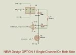
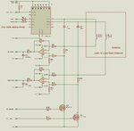
Meanwhile we have got more info from old hardware(We have found one hardware for same Engine, from our local scarp distributor), and presenting new ideas:

1. OLD hardware:

1.jpg

2. New Option 1:

2.jpg

3. New Option 2:
3.jpg
 
Herewith providing our current testing schematic.

Test Infineon.jpg

Please comment on this.
Your valuable replies are saving lots of load here.
Thanks in advance.
 
Yet we are not measuring current due to back emf in above schematic. So we have changed to this.:Test Infineon.jpg

We need help with selecting op amps and or current measuring circuit here. We think if we use same op amp we are facing Common Mode problem.

Yet we need your comments on common mode.
 
Status
Not open for further replies.

Similar threads

Part and Inventory Search

Welcome to EDABoard.com

Sponsor

Back
Top