Vermes
Advanced Member level 4

Attention! Due to high voltage and danger of electric shock, please keep far reaching precautions and comply strictly with this description. The station should be connected only to a grounded outlet, otherwise, in case of breakdown there may be shock. Soldering head should be absolutely grounded! Remember, you make the station at your own risk!
The station has a built-in stabilizing and regulating the performance of air pump system and thereby regulates the strength of heated air blow. The device is also equipped with a heater power regulator, responsible for air temperature at the outlet. Additionally, after turning off the power, air pump cools the head for several minutes, after that the station turns off entirely. But at a voltage of 220V, the station is in standby mode. The whole is in a metal casing. The heater warms up in 5-7 minutes, followed by a full readiness to work. Unnecessary element is the system that delays switching off after the time. Normally speed controller and heating power controller is enough.
The station uses the compensative stabilization of temperature. The metal cover of the heater is used as a heat exchanger. It receives and gives off heat periodically. However, the time in which this exchange occurs is directly proportional to the proper temperature and current strength of exhausted air. This method of stabilization is characterized by a certain inertia. However, this way of regulation is more reliable and beneficial.
With full warm-up of the head, temperature at the outlet was 600 degrees Celsius. The temperature is sufficient to free melting tin-lead alloys, it is ideal for desoldering and soldering electronic systems such as smd and BGA.
Distribution of elements in housing
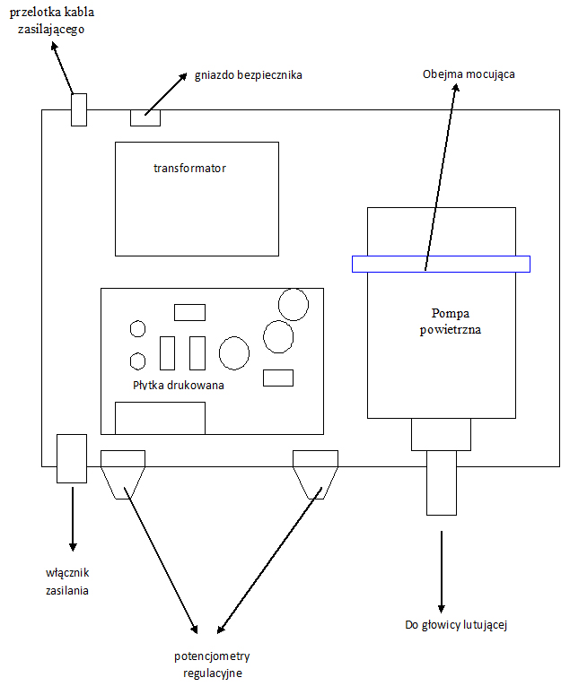
Inside of the station
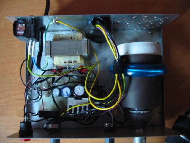
Tinned and enamelled steel housing signed with symbol T-83 was used in this project. The bottom of the housing is covered with polyethylene foam to protect against short circuit if necessary. Another housing made of for example plastic may be used as well.
Construction of the air pump
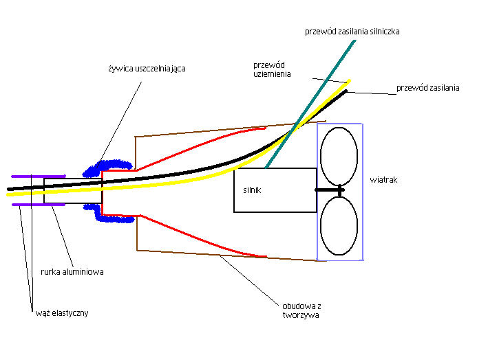
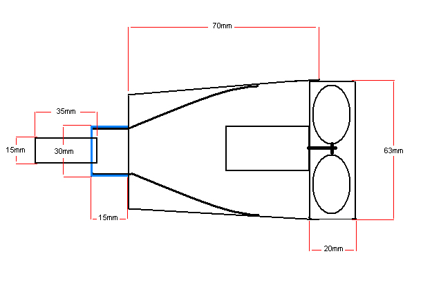
Tube turbine shown in the pictures is the source of the continuous stream of air in the pump. The engine of the turbine is powered by by 12V DC. The whole is made of durable plastic, providing continuous and trouble-free operation of the pump with a fairly large power and the reverse thrust of air.

Construction of the soldering head
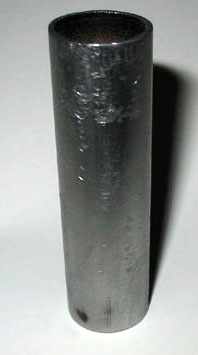
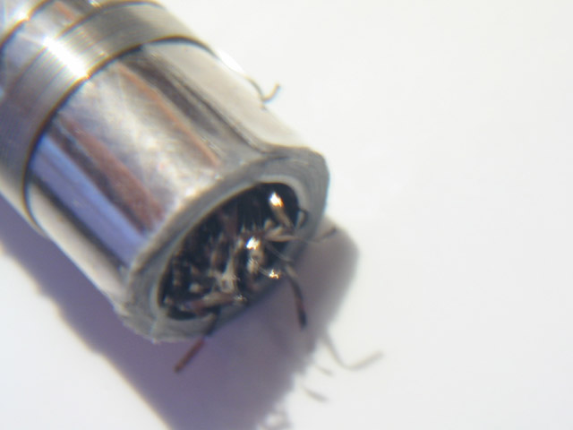
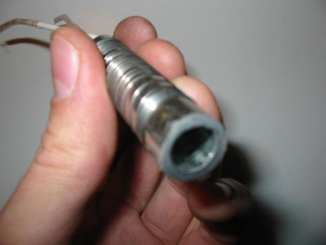
Steel tube, which forms the heating module with the heater.
Chrome-plated brass tube – the basis of the head.

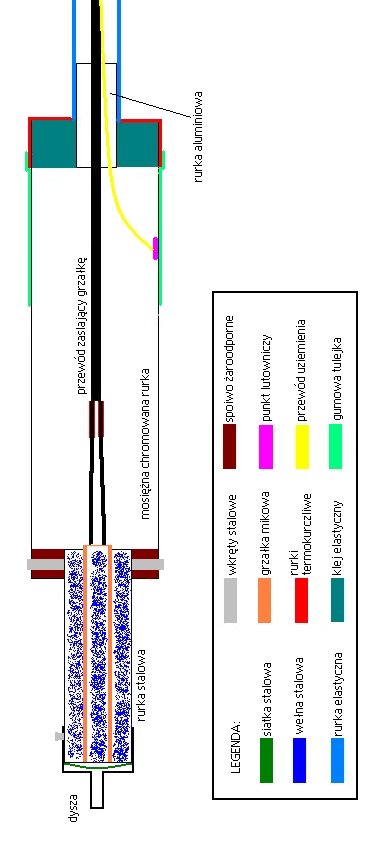
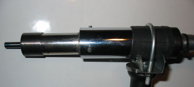
View of complete head
Inside of the heater should be equally filled with wool. Pay attention to the need for free movement of air.

Electronic schema
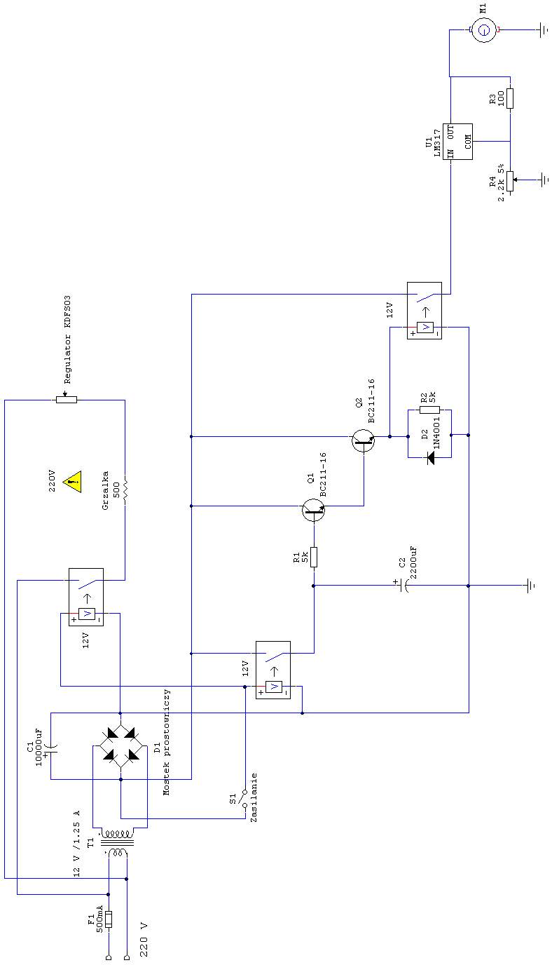
Choosing a capacitor C2, we set the time after which the soldering iron turns off itself.
Power regulator KDSF03 was used as the heater power control.
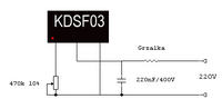
Alternatively, we can use a thyristor circuit shown on the schema below:

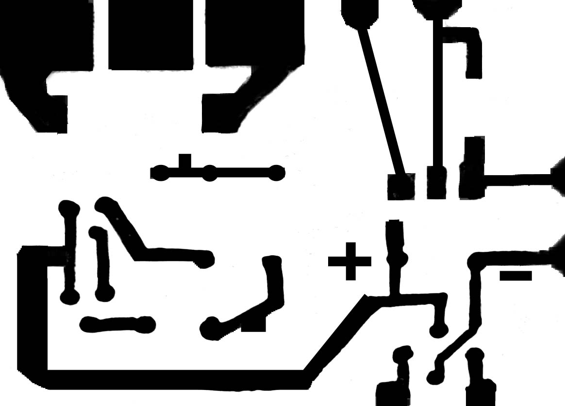
Printed board
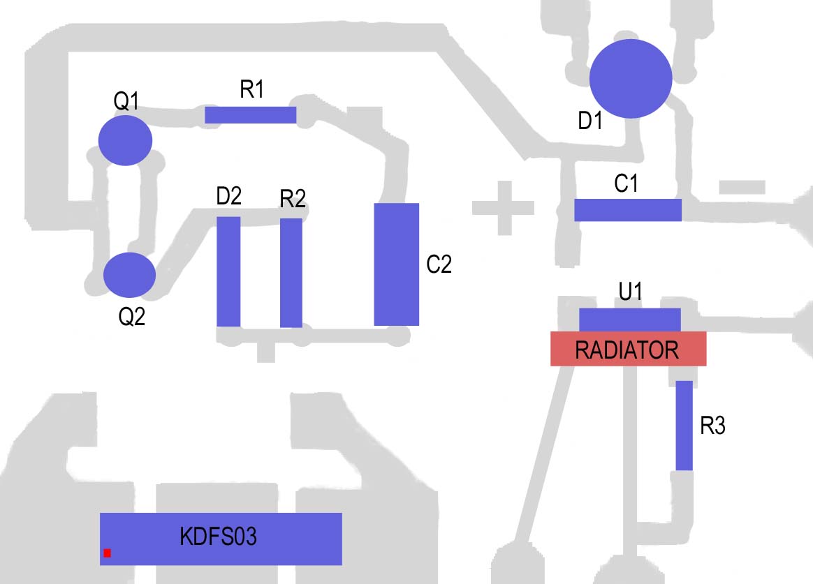
List of components:
- T1 transformer 12V/1,25-1,50A
- F1 fuse 500mA
- D1 rectifier bridge 10A
- D2 diode 1N4001
- C1 10.000uF/25V
- C2 2200uF/25V
- Q1, Q2 211-16 BC
- R1, R2 5 kohm
- R3 100 ohm
- R4 2,2 kohm (potentiometer)
- U1 LM317T
- 12V relay – 3 pieces
- mica heater 500 ohm
- power regulator KDSF03
- 470 kohm potentiometer, capacitor 220nF/400V)
- miniature switch S1
- miniature motor M1
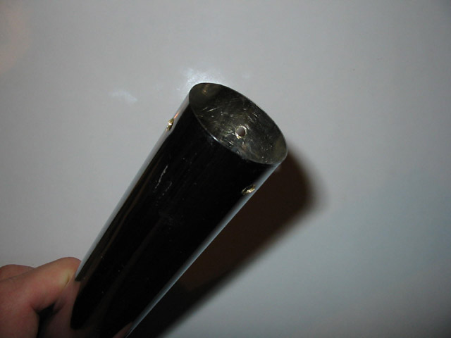
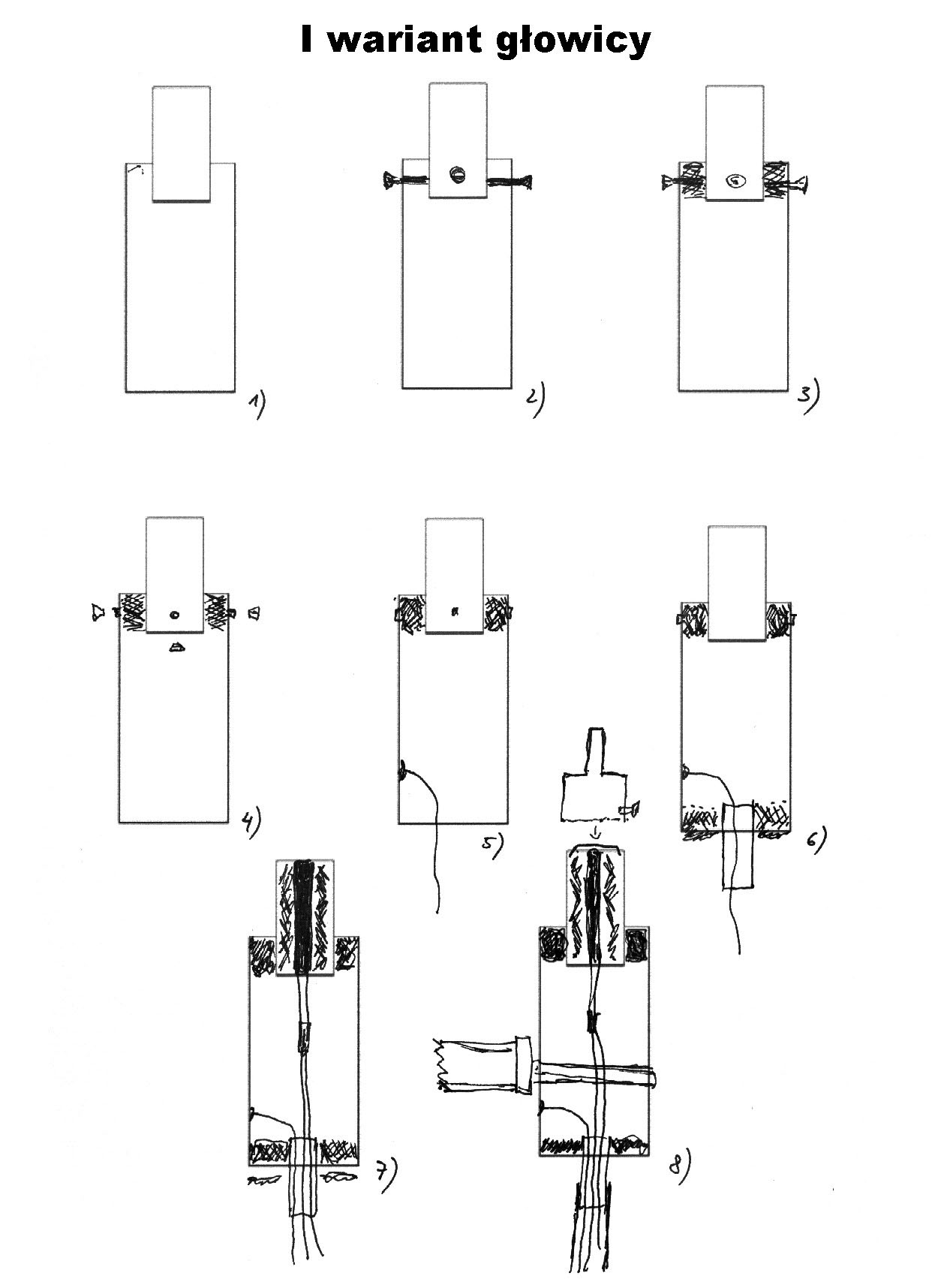
Drill 3 holes in the edge of a brass tube (Fig.2), thread and screw 3 screws m4. Insert a smaller steel tube into the created gap and tighten all 3 screws so that the steel tube was in the middle of the larger one (Fig.2). Fill the gap with heat-resistant kit with a focus on the tightness of the connection (Fig.3).
Kit dries at least 24 hours. Cut off the heads of the bolts m4 (Fig.4) 3cm deep (inside the brass tube), solder the cable which acts as the grounding (Fig.5). Previously, the end of the tube should be warmed up to secure the connection and make it easier to solder (the cable is marked in yellow). The length about 1m. Then put the trimmed aluminum tube in the brass one (previously drag soldered grounding wire-Fig.6). Note: you must firstly cut several deep scratches (with a grinder or a file) on the piece of the tube that will be in contact the adhesive. The connection will be stronger now. The brass tube can also be treated with sandpaper in the middle, so the connection is more stable. Keeping it in the middle and about 15mm deep (Fig.6), very carefully pour hot glue, do not allow the formation of air bubbles. The connection must be very tight. Do not allow to block the aluminum tube. After the glue solidified, cut the superfluous glue with an utility knife and finish it with a lighter. Mount 2 insulated wires (about 1A) about 1m long to the heater. The connection must be very stable, so turn the cables together and tin. Put shrink tubes and heat them with a lighter, then add shirts and heat again. This connection must be perfectly secured (220V).
Cut off the metal ending for mounting steel tip from the end of the heater. This must be done carefully, because the heater is very delicate. Inside of the heater should be filled with steel wool. Free air flow must be kept. Then encapsulate the heater with suitably chosen quantity of wool and insert it in the steel tube. Release the connecting cables on another side (through the aluminum tube). In this way, 3 cables are on the second side (Fig.7). The antenna bracket may act as a handle (Fig.8). Check with an ohmmeter of there is no short circuit between the heater wires and steel housing. Finally, drag 3 wires through the rubber hose and stretch its end on an aluminum tube (after warming up).
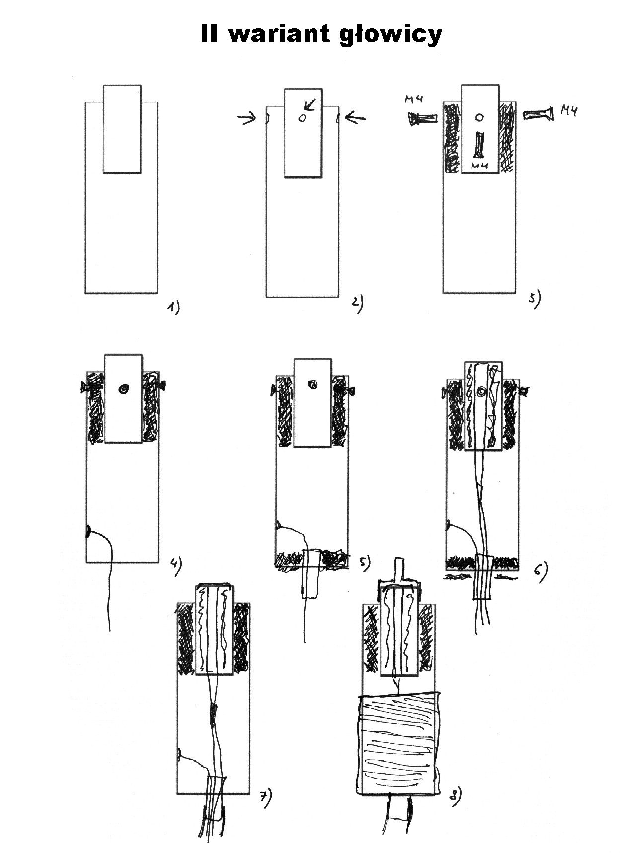
Description of the soldering head assembly: variant II
The length of the chrome tube is 20cm and 7cm – steel tube. Drill 3 holes in the brass tube and thread under screws m4 (Fig.2). The steel tube should come into the brass tube, in order to protrude at about 2-2,5cm.
Special steel wool of low gradulation (Fig.3) acts as isolation. The wool should be well beat, because it has to prevent air for going off. 3 screws m4 were used (screwed after insulating).
The rest as in the variant I.
Instead pistol grip, a handle with imitation leather was used, the end of the tube was several time wrapped in this material or leather and then wounded with insulating tape (Fig.8).
The yellow wire was attached to the housing (if steel) and grounding prong of the outlet.
Soldering head variants
Description of the pump assembly: variant I
The pump uses a fan from the electric dryer (also a different rotor can be used, but it must be of sufficient power).
In the variant I, the pump was constructed with a plastic cover. After cutting a hole in the housing (Fig.1), paste the bottle tip (Fig.2). Stick the edge of the bottle with glue – also silicone for the bathroom can be used and the outlet part should be sealed with poxipol (Fig.3). Melt the aluminum tube in the nut (heat with gas and keeping in pincers melt in plastic nut) and pour with poxipol (Fig.6). Earlier, cut grooves on the tube and the nut from the bottle, so after pouring with poxipol, the whole is strong and stable (Fig.5). Paste a rotor removed from a dryer into this tube. Do not forget about cutting a hole for the high voltage wires near the rotor. This hole should be sealed at the end (Fig.8). Materials used may vary, but it is important to remain the similar idea - good quality turbine (12V) and a nozzle made of a bottle. After mounting the pump in the housing, dozens of ventilation holes should be drilled in front of the fan.
Description of the pump assembly: variant II
Depending on the size of a soldering iron, the pump is made according to variant I, or simply stick a bit of trimmed bottle of drink 0,5l to the end of the dryer (use super glue) and then encapsulate with insulating tape.
Variants of the air pump

Construction of the nozzles
Steel nozzles with the following dimensions were used in this project:
Standard values of dim 1 and dim 2 for universal nozzle are: dim 1=5mm, dim 2=15mm.
Dim 1=3, dim 2=15 for the precise nozzle and dim 1=10, dim 2=15 for the coarse nozzle. In practice, universal nozzle is the best for most applications.
Mounting of the nozzles is M4 screw about 5mm from the bottom edge.
The thinner the wall, the higher operation temperature. Finish the edge marked “dim2” with a file to the minimum.
Self-construction of the nozzle
The nozzle can also be made of copper plug used in central heating installations. In that end a perfectly matched hole should be drilled and a piece of trimmed antenna put in it (antenna tube, for example from an old radio receiver).
Resoldered systems
Link to original thread (videos) – Stacja lutownicza na gorące powietrze - DIY HOT AIR