Vermes
Advanced Member level 4
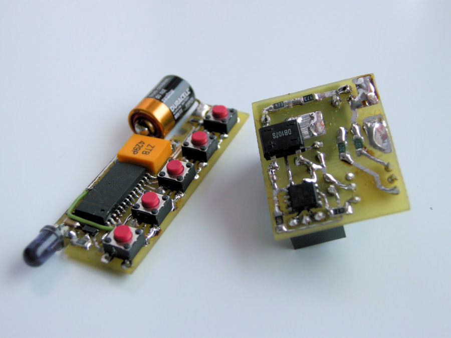
It is a design of device which can be helpful to control lighting in a room. IR control is very convenient for beginning electronics.
Circuit of the remote control was based on an inexpensive chip SAA3010 (equivalent for not produced nowadays chip HT6230). Its advantages are availability in SMD version and small price. Another components are IR diode, transistor, two resistors, resonator and five microswitches. The circuit SAA3010 provides IR remote control in code RC-5, supply in the range of 2-7V.
The whole was closed in a housing for remote. It is powered by Duracell MN11. Supply current is about 2uA quiescent and 2mA when active what prolongs the battery life.
You may need a tester of all kinds of RC-5 remote controls based on Attiny2313.

The remote is to control the dimmer. It is a small construction that requires 4 buttons of a remote transmitting in RC-5 standard.
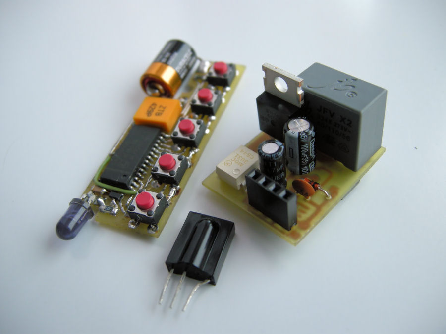
There was one button left of five buttons available, so that it was used to control some devices, mainly the lamp. The socket is controlled using the microcontroller Attiny13 in SMD version and one command in RC-5 code.
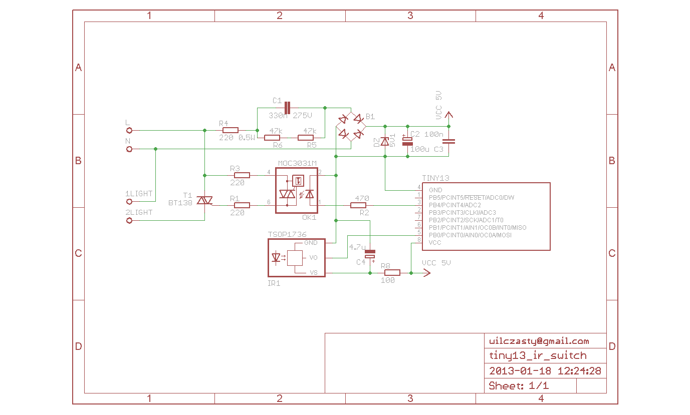
The above schematic shows that the device was intended to be as small as possible. The use of transformerless power supply made it possible to limit its size to the board with dimensions of 3x2,5cm. You can resign from the linear stabilizer, only remember to apply Zener diode 5V1. Receiver TSOP1736 which provides very good receiving of the signal. The whole is controlled by optotriac MOC3010 and triac BT138 (program in the attachment to the original thread).

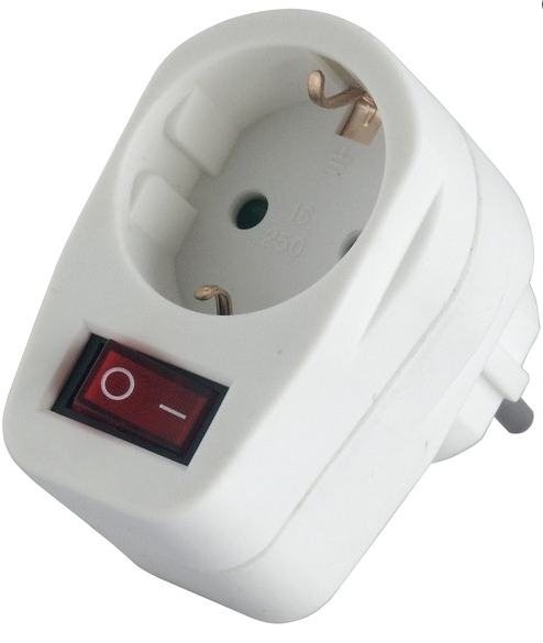
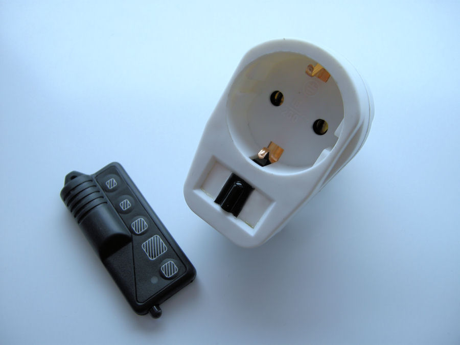
The entire device can be placed in a KM-49D type housing with 230V socket. As well you can use a socket with circuit closer (showed below), pull out the circuit closer, make some room inside so that you can place the PCB, instead of the switch, you have the IR receiver.
Link to original thread (useful attachment) - Gniazdo sterowane z pilota IR