Continue to Site

Welcome to EDAboard.com

Welcome to our site! EDAboard.com is an international Electronics Discussion Forum focused on EDA software, circuits, schematics, books, theory, papers, asic, pld, 8051, DSP, Network, RF, Analog Design, PCB, Service Manuals... and a whole lot more! To participate you need to register. Registration is free. Click here to register now.

Snubber Circuit Design 230V, 16A, Problem in small load, Current Flow!

Status
Not open for further replies.

snajperisti

Newbie level 4
Joined
Aug 18, 2020
Messages
6
Helped
0
Reputation
0
Reaction score
1
Trophy points
3
Activity points
33
Hello
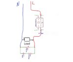
We designed this Snubber Circuit with this varistor in parallel but we have a problem in a small load. Even when the relay is disconnected, a small current is flowing. For example, when connecting a phone charger, the phone screen keeps turning on and off.
The varistor is Hongzhi Elec 7D471K
The resistor is 2.2 ±5% 1W ±350ppm/°C Axial,3.3x9.2mm Carbon
The capacitor is 100nF ±10% 275VAC 10 Through Hole,P=10mm Suppression Capacitors

I think the problem is with the capacitor and maybe I need a smaller one to increase the impedance and limit the current flow or schematic problem.
1597750666124.png
 

The problem is almost certainly due to natural reactance in the capacitor. The effect of the resistor is negligible but at 60Hz the capacitor has a reactance of ~26K and at 50Hz it is ~31K, probably low enough that enough current can flow into your load to operate it.

Consider placing the R and C across the input and load side rather than across the switch. The Varistor is probably not causing the problem but assuming any spikes are produced by the load, you could place it across the load or even use one on each side of the switch if you suspect mains borne transients.

Brian.
 
make sure the cap is 275Vac or better, & welcome to the world of snubbering for AC ....!
hahahahaha, yeah the capacitor is 275VAC
--- Updated ---

The problem is almost certainly due to natural reactance in the capacitor. The effect of the resistor is negligible but at 60Hz the capacitor has a reactance of ~26K and at 50Hz it is ~31K, probably low enough that enough current can flow into your load to operate it.

Consider placing the R and C across the input and load side rather than across the switch. The Varistor is probably not causing the problem but assuming any spikes are produced by the load, you could place it across the load or even use one on each side of the switch if you suspect mains borne transients.

Brian.
Okay, we will test it and hope for better results.
Thank you.
 
The problem is almost certainly due to natural reactance in the capacitor. The effect of the resistor is negligible but at 60Hz the capacitor has a reactance of ~26K and at 50Hz it is ~31K, probably low enough that enough current can flow into your load to operate it.

Consider placing the R and C across the input and load side rather than across the switch. The Varistor is probably not causing the problem but assuming any spikes are produced by the load, you could place it across the load or even use one on each side of the switch if you suspect mains borne transients.

Brian.
Hey Brian,
We tried this connection of snubber circuit and till now the tests are going well and we are not having any problems.
Another problem that this snubber solved for us was the resetting of the microcontroller in our PCB.
 

Attachments

  • snubber2.jpg
    snubber2.jpg
    48.5 KB · Views: 312

Here are some simulations for the snubber in relay contact and in load. The effect of the snubber is okay in both cases but in the load there is no current leak.
1597844060785.png
 

Status
Not open for further replies.

Similar threads

Part and Inventory Search

Welcome to EDABoard.com

Sponsor

Back
Top