StevenHart
Newbie level 5
Hi,
I have an unstable 50V output from my SMPS and I am finding it hard to explain why.
I am quite new to SMPS design and have inherited this design but I believe there is a flaw in the design.
I am using two LTC3862-2 in a master-slave configuration to generate a 50V, 52.5V,85V output.
The output voltage is stable at 85V but at 52.5V and 50V the output of the SMPS becomes unstable.
The output voltage is perfectly stable at 50V when there is NO load, but applying a load then causes the output to become unstable.
Here is the schematic for my SMPS. There are a few enable pins going to a microcontroller to alter the potential divider feedback.

According to the datasheet, for a multiple device topology, the following application should be used...

The main difference I can see is my 'ITH' pins are connected separately. I am also not using 100k resistors between feedback pins, as this is quite a sensitive line, could this be having an affect?
Despite the differences, I do not believe this is the root cause though. I measured the output voltage of the 'ITH' pin, and the voltage was just as unstable as the output, varying between Current limit and overload conditions. Also probing the 24V supply to the device and the inductors, an approx 1V drop could be observed. The volt drop can be seen at the PSU which points at the load. Both of these instabilities were in line with the output voltage instabilities. This lead me to the gate drive behavior...

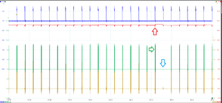
Blue - Load demand (used as trigger point)
Red - Output Voltage (AC coupled)
Green - Gate 1, of master device
Gold - Gate 1, of slave device
It can be seen from the gate behaviour that something is telling the gate to drive a bit harder/longer (green arrow), thus increasing the output voltage (red arrow). This is then compensated with no gate driving condition on the next load demand (blue arrow).
What could be causing this decision?
The same trace for the 85V shows a very consistent output (red), with consistent gate drive behaviour...

Does anybody have any ideas what is causing this?
Any help would be appreciated. I don't what else to check or where else to go from here
Thanks,
I have an unstable 50V output from my SMPS and I am finding it hard to explain why.
I am quite new to SMPS design and have inherited this design but I believe there is a flaw in the design.
I am using two LTC3862-2 in a master-slave configuration to generate a 50V, 52.5V,85V output.
The output voltage is stable at 85V but at 52.5V and 50V the output of the SMPS becomes unstable.
The output voltage is perfectly stable at 50V when there is NO load, but applying a load then causes the output to become unstable.
Here is the schematic for my SMPS. There are a few enable pins going to a microcontroller to alter the potential divider feedback.
According to the datasheet, for a multiple device topology, the following application should be used...
The main difference I can see is my 'ITH' pins are connected separately. I am also not using 100k resistors between feedback pins, as this is quite a sensitive line, could this be having an affect?
Despite the differences, I do not believe this is the root cause though. I measured the output voltage of the 'ITH' pin, and the voltage was just as unstable as the output, varying between Current limit and overload conditions. Also probing the 24V supply to the device and the inductors, an approx 1V drop could be observed. The volt drop can be seen at the PSU which points at the load. Both of these instabilities were in line with the output voltage instabilities. This lead me to the gate drive behavior...
Blue - Load demand (used as trigger point)
Red - Output Voltage (AC coupled)
Green - Gate 1, of master device
Gold - Gate 1, of slave device
It can be seen from the gate behaviour that something is telling the gate to drive a bit harder/longer (green arrow), thus increasing the output voltage (red arrow). This is then compensated with no gate driving condition on the next load demand (blue arrow).
What could be causing this decision?
The same trace for the 85V shows a very consistent output (red), with consistent gate drive behaviour...
Does anybody have any ideas what is causing this?
Any help would be appreciated. I don't what else to check or where else to go from here
Thanks,