Continue to Site

Welcome to EDAboard.com

Welcome to our site! EDAboard.com is an international Electronics Discussion Forum focused on EDA software, circuits, schematics, books, theory, papers, asic, pld, 8051, DSP, Network, RF, Analog Design, PCB, Service Manuals... and a whole lot more! To participate you need to register. Registration is free. Click here to register now.

SMPS transformer testing

Status
Not open for further replies.

chirag2239

Member level 3
Joined
Jul 29, 2011
Messages
64
Helped
1
Reputation
2
Reaction score
1
Trophy points
1,288
Activity points
2,048
Hello,

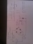
I have created a transformer which would be used in my power supply design. I have designed a supply by using just a capacitor of 0.1uF, 400V which is polyster capacitor, a bridge, resistor of 630k/2W in series and then zener diode of 6.3V,1W in series with 330k/1W resistor. Then I have heard that if this circuit will work then we cannot have isolation between input and output. so I have a risk of electric shock. So I want to put a isolation transformer that is generally used in mobile phone charger and SMPS for isolation.

So I have just created it and now I am confused that I have designed it for 240AC 50Hz input and now I am going to use it after bridge for isolation. So how do I test it?

Is there any process to test the SMPS transformer that is it working or not? Can I use it after the bridge which is DC voltage and I have applied 240V AC to bridge?

I have attached my schematic and in this schematic I have mentioned my questions that I want to do.

Kindly help me to solve my problem.

Thanks.
Chirag
 

Attachments

  • WP_000049 (2).jpg
    WP_000049 (2).jpg
    1 MB · Views: 116

Hi Chirag,

There are lots of things wrong with that drawing!
Assuming the 240VAC is the input, the bridge rectifier is not oriented correctly, the inputs and outputs are mixed up!
Assuming the rectifier fault is corrected, you are going to get DC voltage on that 10uF filter capacitor.
A transformer does not work with DC voltage/current!
You need to put the transformer at the AC input of the circuit to achieve isolation and still have functionality.

But to start with, you need to specify the requirements, like output voltage, current, e.t.c.

Regards, Peter
 
Last edited:

Yes transformers only work with applied AC in and give only AC out, even a tiny amount of DC on the driving side of a Tx will affect it badly, a small ferrite Tx needs to be driven at high frequency >>50kHz, (not DC). I'm sorry but your whole premise is wrong here.
 
Hi,

Thanks for help.

Please see the attached image and guide me.

I have a question that why we place PWM controller at the auxiliary of the isolated transformer?
Can we make power supply without PWM controller using isolated transformer?
I have heard that isolated transformer works on DC and it damages on AC. Is this correct?
Please see the attached file and guide me.
I need to place a very cheaper power supply that converts AC into DC without any problem. the simple one that I have found from internet is little risky because if we do not isolate the input and output of the supply, we can not touch the circuit while the circuit is on. Where my application is microcontroller and WiFi based. I want to Switch on and off the home appliances through Arduino over WiFi. So I have to provide the logic of ON and OFF state of the switch to the arduino pin. For that I have to convert 240V AC in to 5V,with lower current DC. Can anyone guide me?

That's why I want to use the isolated transformer. I can operate evenif the supply is on and there is no harm due to non isolated supply on controller board. I can not use adapter because it costs high. If I can put the simple and cheaper converter like SMPS on the board, then I just have to connect mains to the board.

That's all.

Please help me to guide through this project. I will be thankful to you.

- - - Updated - - -

can pulsating DC will work? I mean if I will connect the diode at the AC mains and then I will not filter the signal, and outour of diode which is pulsating DC, can it be allowed to fed to transformer? I do not want to use PWM microcontroller so please suggest me a way to use isolated transformer with the circuit without using PWM controller.
 

Attachments

  • WP_000050.jpg
    WP_000050.jpg
    1.2 MB · Views: 98
  • WP_000051.jpg
    WP_000051.jpg
    1.1 MB · Views: 93

You need to understand the options available to you:


AC -> Transformer -> Rectifier -> DC Output

That's the simplest AC to DC converter you can make. It's "unregulated" meaning the DC voltage is entirely dependent on the turns ratio of the transformer.


AC-> Transformer -> Rectifier -> Linear Regulator -> DC Output

That's the same but with a linear regulator at the end. This is simple, isolated and provides a well regulated output. But it's large, heavy and inefficient compared to more advanced designs. It sounds like this may be what you want.


The reason supplies have PWM's is that it lets them chop the 60Hz AC into a much faster frequency and a faster frequency means smaller/cheaper magnetics (transformers can only pass AC!). Switching also provides a mechanism for regulation that's more efficient than linear options.
 

AC>transformer>rectifier>DC-DC has poor performance in transformer, diodes and capacitor due to low line frequency and large Caps cause high surge currents, poor power factor etc.

AC>rectifier>DC>AC>transformer>rectifier>DC has much better performance since higher switching frequency reduces core and capacitor sizes.

Although ideal design uses two transformers, one for primary AC-DC with 10kV isolation, and active PFC and one for DC-DC for efficient power control.
 

AC can be thought of as alternating pulsed DC, but the pulsed DC must be carefully applied to a suitable transformer, (same volt-second product applied each way!)
 
Status
Not open for further replies.

Similar threads

Part and Inventory Search

Welcome to EDABoard.com

Sponsor

Back
Top