Continue to Site

Welcome to EDAboard.com

Welcome to our site! EDAboard.com is an international Electronics Discussion Forum focused on EDA software, circuits, schematics, books, theory, papers, asic, pld, 8051, DSP, Network, RF, Analog Design, PCB, Service Manuals... and a whole lot more! To participate you need to register. Registration is free. Click here to register now.

SMPS output voltage slow increasing

Status
Not open for further replies.

elefant

Newbie level 5
Joined
Jan 4, 2021
Messages
8
Helped
0
Reputation
0
Reaction score
1
Trophy points
3
Activity points
90
Good day!

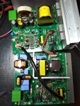
I have SMPS made in Korea, KSB Seil model SMPSS10A. I couldn't find any circuit diagram for that power supply. I'm not well experienced in solving electronic problems so i need some help.

After switching on it has 0 V output. After few minutes it starts to increase slowly and finally reaches its rated output 24 Volts. It doesn't matter whether load connected or idle. Only if it has reached 24 V and I switched off the power and immideately switched it on then ouput voltage become 24 VDC instantly. If i give this SMPS some "cooling" period without mains and then switch it again, so then it start to increase outut as it was described above.

I checked primary circuit, it gives stable 390 VDC after rectifier. This voltage is coming to power transistors input. But output from these transistors is zero and starts to increase only after few minutes.

So please give me some advice what elements i should check first. Or maybe somebody could help me to find circuit diagram for this power supply.
 

Hi,

A few minutes?! I'm no SMPS expert, so ignore me... Without a schematic or photo of the pcb it would be conjecture for many.

Maybe it has 100 Farad output capacitors ;).

Maybe the control loop has large capacitors.

Maybe it needs warm-up time so has a programmed delay.

Might be worth seeing (measuring) what is driving the transistors.
 

No,it has no any large caps)))
It is not normal for this power supply,it is failure.I have same units in other equipment and they work properly and reach rated output instantly.
 
Hi,

We don't see anything of the faulty circuit. Thus we have no chance to validate anything.

All we can do is guess.
* Bad solder joint
* Bad capacitors
* defective chip
* ...

*****
What about a photo?
And some part names, especially of the SMPS IC..

High voltage is dangerous. Are you experienced and careful enough to do some measurements?
Do you have a scope with useful probes?

Klaus
 

Maybe startup resistor has gone to extremely high resistance. What controller is it using. Probe the vcc of the controller. What voltage is it?
I assume it is offline flyback? Does it have a micro in it?
 

Sorry, i've tried to attach photo of circuit in my first reply, but my phone failed to do that. Now i better use laptop.

I'm experienced enough with high voltages and have scope to make measurements.
Unfortunately,this PCB is left in my workshop, so i can tell you the names of IC only tomorrow morning,also the measuremnets of vcc on them.

What about bootstrap circuit, i don't know, because i'm not familiar what it means,sorry:rolleyes: I'll try to learn it tonight.

Some comments to the photo.
Lower circut is hot side, with mains. Thick red and black wires - rectifier output with 390 VDC,it is stable all the time. Then it comes to the power transistors (to the right from wires solder points), but nothing comes from transistor output as i described above.
Tomorrow i'll look for the names of ICs and try to do VCC measures on them
 

Attachments

  • IMG_20201224_091153.jpg
    IMG_20201224_091153.jpg
    5 MB · Views: 284

Your PCB seems to have a pfc stage and then a DCDC stage.
Separate the two to see which one is causing the delay.
Eg you could power the DCDC from a 390VDC supply and see if delay is still there.
But i bet there is a dry joint somewhere.
 

What about bootstrap circuit, i don't know, because i'm not familiar what it means

It generates a voltage high enough to turn on an NPN or Nmos, if such an N-device is installed nearest to the positive supply. It works like a voltage doubler. External components include a resistor and capacitor. To charge the bootstrap requires a few cycles during power-up.

A fault in the components could extend charging time to seconds or minutes.

But then once charged it keeps its charge. This would explain why you can disconnect power briefly, yet the smps resumes operating normally as soon as you re-connect power.
 

There are following ICs:
Primary switcher VIPer12ADIP
PFC controller L6562
Output PWM controller TL494
 

Did you see if it was the PFC stage or the PWM stage that was causing the delay.
(Do not probe the circuit unless you know what you are doing.....there are voltages there that can kill you)

L6562 is your PFC controller
Viper12 is your bias power supply
TL494 controls the downstream switcher.

They all have datasheets you can download, and find the vcc pin. Do you have an isolated probe? (diff probe) rated to the voltage?
Check their Vcc pins with scope.
Is the viper having difficulty starting up?
 

I checked VCC voltages on ICs.

Voltage on downstream controller TL494 was 4.5 V at startup moment and was increasing slowly. Maybe this is the reason of my problem&
Voltage on Viper12 was 14.5 V and was increasing but with lower rate than on TL494

Voltage on L6562 was about 15 V but then unfortunately shit happened. I work at sea on the ship and it was rocking today. It is difficult to keep balance and make precise movements. SO occasionally i touch two pins with my probe and most probably short pin 5(boost inductor's demgnetisation sensing input) to pin 6 (GND). Fuse has blown, and now I have short circuit on the output of rectifier bridge. So I have to find out this at first before i continue to track the reason of low output voltage.
 

ok well done, i feel sorry for you....its a shame they cant get you a gimble thing to work in which coutneracts the ship rocking....or let you work in the "zenith" of the ship, where the rocking is minimal.
4.5V is not enough voltage on the TL494..
So at this point, it looks liek the startup circuit of the TL494 is getting problems......is it starting via a startup resistor to the high voltage rail?......has this gone semi-dry?
We are going to have a job here as it sounds like you have no schematic.

incidentally, TL494 is a very old controller............so i wonder if it is an old power supply...and something has finally gone dry joint somewhere.....or maybe the startup capacitor has dried out or something.

There was no need at first to probe the L6562...you could probe the vout on the PFC output cap...and if it is 390V or so then thats ok.
Remember we want to see what is broke...is it the pfc stage or the PWM stage.

Do you know about pfc stages? ..You get the mains rectifier, then the pfc stage, then the downstream pwm stage.
Be careful, there are killer voltages on that circuit of yours !!!

When you replace the fuse, do you have access to an AC source which allows you to gingerly increase the AC inut from 0v...or an autotransformer?..........put a current monitor in there so you can see if its drwing too much current when you start the ac input from low volts...this way you can gingerly see if the short is still there....without blowing the thing up.
A thermal cam is also very good for seeing shorted things.
--- Updated ---

I know its hard for you...but best not probe like you do...you slip and blow up.....turn off...solder a flying probe leads on, then connect probe to the flying leads.....then turn on and probe the flying leads.
Kynar wire is good for making flying leads
 
Last edited by a moderator:

Rolling counteracting systems are used only on passenger ships. I work on crude oil tanker,so we don't have this. My workshop is located in engine room, which is almost at "zenith" as you say, but main magnitude of rolling is not a main problem. When you go through rough sea waves then vibration always follows you everywhere, so to solder just two wires become a real hard task:)

I don't know how old it this power supply but our ship is built in 2016 in Korea. Korean ship engineers like to use old components and systems, there a lot of stuff from 2000-s onboard.

What about my circuit. Unfortunately I have no autotransformer.There are no 380 VDC, and input AC fuse blows after switching on. As i told in previous message, i measured short circuit on output contacts of rectifier bridge. Shunt capacitor is OK, I suspected primary winding of transformer (big yellow on the lower PCB on the photo), so i removed it from PCB and after that tried to switch onthic circuit. Fuse didn't blow but some part started smoking. I switched it off immideately. Maybe tomorrow i'll try to use 24 VDC lab power supply (only adjustable source i have) and infrared camera but i'm afraid that i've already destroyed this circuit:)
 

Sorry to hear this.
Just to check, you did use an isolated probe? I am sure you know you cannot use a normal oscilloscope and oscilloscope probe to probe the primary side of an offline power supply.
You say you are on an oil tanker...i am not sure what the mains is like on an oil tanker, i suspect possibly you might have some pretty big mains transients which might give grief to a power supply.
 

I'm not sure what do you mean as "isolated" probe but i suppose that it means measuring signal with just one probe while oscilloscope is connected to the ground.
I have portable Fluke oscilloscope and make measurements like with usual multimeter. Put one probe (common) to ground (zero potential, or negative, or minus lead,whatever),the other probe i put to the point where i want to get signal.

What about transients-we don't have significant sources of transients. We have bifg frequency converter for propulsion but firstly it is connected via transformer with two secondary windings (star and delta with angle of 30 degreees to remove harmonics),and secondly this converter always control synchronous motor in manner to keep power factor equal to one. So THD in our mains are negligibly small, about 1%.
 

I'm not sure what do you mean as "isolated" probe but i suppose that it means measuring signal with just one probe while oscilloscope is connected to the ground.
I have portable Fluke oscilloscope and make measurements like with usual multimeter. Put one probe (common) to ground (zero potential, or negative, or minus lead,whatever),the other probe i put to the point where i want to get signal.
So was your probe powered only by batterys when you probed the power supply? (i hope so)

A "normal" oscilloscope has the dangling ground clip of the probe connected to the mains supply earth.
If you clip that to a place on the primary side of an offline (ie mains connected) power supply then you will get an explosion.
I hope that your scope was not plugged into the ship mains supply when you used it?
If you have the scope plugged into the ship's mains supply, then you need an isolated probe like this....

TA041 by pico
**broken link removed**

I presume that the "earth" in a ship's mains electricity supply sockets is connected to the metal hull of the ship, but i dont know for sure.
 

Ok, i got it. I have portale oscilloscope supplied by batteries and isolated from ships mains. As i told before i use it like usual multimeter.
 

Status
Not open for further replies.

Similar threads

Part and Inventory Search

Welcome to EDABoard.com

Sponsor

Back
Top