Continue to Site

Welcome to EDAboard.com

Welcome to our site! EDAboard.com is an international Electronics Discussion Forum focused on EDA software, circuits, schematics, books, theory, papers, asic, pld, 8051, DSP, Network, RF, Analog Design, PCB, Service Manuals... and a whole lot more! To participate you need to register. Registration is free. Click here to register now.

[SOLVED] Size of rectifier bulk capacitor for a DC/DC converter.

Status
Not open for further replies.

David_

Advanced Member level 2
Joined
Dec 6, 2013
Messages
573
Helped
8
Reputation
16
Reaction score
8
Trophy points
1,308
Location
Sweden
Activity points
12,217
Hello.

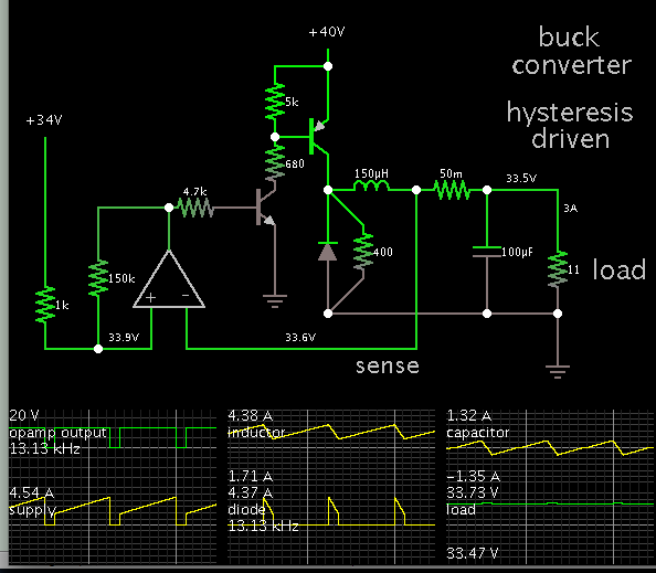
I am designing a pre-regulator which is a step-down converter stepping down just under 40Vdc(28Vac rectified) to 3-33Vdc 0-3A, cost is a big obstacle to overcome since this is no big production and I will only make 3 PCBs to begin with.

I recon I need at least 80V rated capacitors for the input but how much capacitance do I need?

By the way, I'm using a active rectifier with MOSFETs.

Regards

- - - Updated - - -

Hmm, I might have to scrap the active rectifier.
I have never used them before and it seams as a big capacitor bank right after them is not a good idea.
 

Hi

I would suggest you to put a 100nF cap in parallel with 1uF and 10uF. This is what I usually do for step-down converters of this range.

Cheers
 
  • Like
Reactions: David_

    David_

    Points: 2
    Helpful Answer Positive Rating
What is the maximum duty cycle of your buck converter?
What are the IR losses in the mosfet and inductor?
These two questions give you the minimum voltage that must be maintained at the buck input for the thing to remain in regulation.

What is peak DC bus voltage at lowest possible mains and full load?
The difference between this and the value found above gives you the allowable worst case ripple voltage.

Then assume a 3A load (slightly pessimistic, but that is the way to bet) and a 10ms period, and dv/dt = I/C and you can get a minimum value for the cap.

For prototype quantities, cost is almost never an issue, try designing for a run of 1,000,000 units in a cost constrained market sometime!

I would go with 63V caps BTW, and would figure that with only a few volts of allowable ripple you may be looking at several thousand uF of bulk cap (And remember to watch the ripple current ratings!).

Regards, Dan.
 
  • Like
Reactions: David_

    David_

    Points: 2
    Helpful Answer Positive Rating
Depends on the ripple voltage and ripple current. Calculate the capacitance by using these.
 

I have always found it hard to find any info on how to do this online, but I guess I need to look harder.
But how does the ripple effect a buck-converter?

If it was a linear regulator the ripple would simply be attenuated by some degree found in its datasheet, but a buck-converter which switches the voltage/current in square waves might be less sensitive to input ripple(just a wild guess)?
 

If it has quick feedback response, then a buck converter will be able to adapt to ripple on the supply input. The ripple is 100 or 120 Hz, comparatively slow to a converter operating at 10 or 20 kHz.

In case this is of interest, here is my simulation of a simple buck converter which produces regulated output voltage. It is hysteresis-controlled via op amp.


The sense wire is located strategically. Part voltage control, part current control. This provides tight feedback response. Regulation is 1 or 2 percent. A sufficient smoothing capacitor value is on the same order as the inductor. (Notice it has substantial current going back and forth through it.)

The 400 ohm resistor is unnecessary. It is there so the simulation runs smoothly.

If you wish to reference the output to 0V, it is handy to use an NPN and PNP transistor as shown. Or you can use your own arrangement.
 
  • Like
Reactions: David_

    David_

    Points: 2
    Helpful Answer Positive Rating
I doubt that achieving 33V regulated output with 28 VAC input is a reasonable design. You must be aware of line voltage variations and transformer voltage drop. 40V bus voltage isn't but an ideal number. In addition the input voltage ripple futher reduces the regulation margin. Trying to make it too small by oversizing the capacitor results in higher input peak currents and respective increased transformer and rectifier losses.

I'm also not sure if "active rectifier" is a good choice regarding ruggedness.
 
  • Like
Reactions: David_

    David_

    Points: 2
    Helpful Answer Positive Rating
I have been wanting to build a mains monitor system to plot the variation where I live, I have scrapped the active rectifier circuit. I had not considered the fact that the one-way conduction of diodes not only rectifies the voltage but also help maintain the charge on the bulk capacitor from being drained when the voltage waveform drops to 0V.

If I would push the design I really only need about 31V output from a buck-converter, I had not thought about it but I have been under the assumption that I will get around 39,6V from the rectifier and although I did know about the losses to be aspected I did measure 39,5V but that was under a quite light load which I think would result in a higher than rated voltage from the transformer. I keep forgetting to do so but I will need to test the transformer for real to find out the load regulation.

If need be I'll guess I'll go for a buck/boost regulator to compensate.
Anyway I will return when I know for sure how the transformer will perform.

Thanks
 

wow, I must have made a mistake and thinking about something else since the answer to this question was the easiest google search I've ever made:p

If we assume that the ripple voltage is small in comparison to the rectifier input voltage, and using full wave rectifier, and don't mind looking at the charge/discharge curve is linear then:
Iload/f*C = Vripple
where Iload is Ampere, f is Hertz, C is Farads and Vripple in Volts peak-peak.
Note that it is only an approximation.

I find it difficult to provide more than 4-5000µF, or if space is made a 10,000µF can be fitted if the high cost for such a cap(the rectified voltage is a little below 39V, so 80V tolarent cap is needed?) then:

3A/100Hz*0.004700F = 6.38Vpk-pk
or
3A/100Hz*0.010000F = 3Vpk-pk

I wonder if I can get away with ~6Vpk-pk ripple at the input to my buck converter...
It will feed a linear regulator to be used as a lab supply, can a switching step-down regulator tolerate that high ripple. What do you think?

- - - Updated - - -

By the way, as soon as my computer stops crashing I will check out that simulation.
I don't know where my head as been since I noticed that post only know....
 

Hi David,
With a typical 28VAC transformer you will get 28-30VDC at 3A load. With 6V ripple your low voltage is 25-27V, you wont be able to get 31VDC 3A output.
Since you are using a switcher that normally has high efficiency you would have been better of with a higher AC voltage because it reduces the input current to the inverter and also the value of the cap. It also allows you bigger ripple and that reduces the cap even more.
 

The transformer is rated for 5A and I have known for a while that it is in the lowest voltage range possible if at all. I#ve bought this in a very early stage of my electronics learning and did not know better.

But I suppose I need to lower my final output voltage, I have had it in my head for a long time of ending up with a 0-30V output. The linear regulator I have should be operating with no more than 290mV drop out but the output of the regulator is driving the base of a NPN darlington which I guess would ad about 1,4V so setting the switchers output 2V above the linear regulator stage should suffice if I am not missing some aspect of it all.
I have begun the idea of using a opamp based swtching circuit as well.
 

This concerns me quite much, I have had the same check on this thread as I always do. Or so I thought but I have missed the hole thing and I now notice that I have gotten all the answers I need already:)
I can't imaging how I could have missed all this, anyway. Thank you all very much
 

Hi David.
The max regulated output voltage you get is:
VDC unregulated under load - 10% (drop in mains voltage in winter) - half ripple - regulator voltage drop.
You will find that the unregulated DC with no load and mains at +5% is about twice the value of max load min mains. You have to use this for selecting your caps and diodes.
In your case I recommend to build your power supply with 80V cap and a regulator that you choose and measure the max regulated voltage that you get. If it is good for you then you win, if the voltage is too low for your need you can correct it. If you need an extra 5VDC get a transformer of 3A or 5A 5VAC and wire the secondary in series to the secondary of 28VAC.
Michel
 
  • Like
Reactions: David_

    David_

    Points: 2
    Helpful Answer Positive Rating
Hm, I had never thought to use two transformers in such a configuration. Great idea.
I had initially selected 80V electrolyte's and 100V ceramic's, but the cost of this project is starting to become a problem seeing as I don't have a employment right know and for the first production of this circuit I will probably go with 63V electrolytes if that does work. I have no experience but I think without knowing for sure that 63V will be fine only that the life expectancy will be degraded?
Or so I have read I guess.
I have more or less decided that I need to etch a test board for which ever switcher I use to see the results, when I wrote that it seems as a obvious necessity.
I have read about and heard about variations in the main voltage but I will start making a arduino based circuit to measure the mains in my home over long periods, over one year I guess.
Would you have any suggestion for how tightly I should read the voltage?
I use a arduino Due which as quite a big storage space but I will probably use a sd card as well, but I have no clue if its appropriate to read the mains voltage once a minute, fifth minute, each hour or a couple of times a day...
Any suggestions?
 

Electrolytic caps have shorter life from heat only. it evaporates the electrolyte. Keep the caps away from the heatsink and the transformer. You are OK with 63V cap up to 63V, since the supply is not for NASA you don't need big safety margin.

To save on cost you can buy components directly from China, in many cases the cost is less than 25% in compare to Europe. The wait is long but shorter than the wait for the global warming to arrive in Sweden.

To qualify for CE mark equipment has to be tested to 230VAC +5%/-10%. In cities the mains voltage is mostly within this range. In remote places it can be anything. We are 8 houses in the country sharing 50KW transformer, when my neighbour starts his air compressor my computer reboots and the lights go off for a second.
To my opinion it is enough to measure your mains once in the day and once at night. If you wish to record the mains voltage every second it can be an interesting project. If you collect results of one year it will take you 5 years to analyze the results.
I think you have to build your arduino mains monitor and leave it on until you have another use for the arduino, and that will give you enough fun.
 

Ok, Where do you find these deals?
I sometime buy from Chine through eBay but I have not bought passive components.
One time I wanted a LM338, from Elfa Distrelect in Sweden the price was 93SEK ~10USD for one unit, and I bought 10 of those shipping for free for something like 80SEK....
the 6 of them that I have used have worked perfectly and it is just the same as the one at Elfa I believe

Is there any particular reason to why you never see surface mount components in under large electrolytes? It might be different commercially but in this project I find that the area of PCB occupied by the main bulk capacitor(10,000µF 30mm diameter) cost as much as the capacitor and I have resorted to let the capacitor extend over SMD devices that are lower than 2mm to save space and cost.
I can't see any obvious disadvantage in doing this except for the increase of the connection parasitic of the bulk capacitor but how much could this really add, in a use such as this it could hardly matter anyway?

Do you mean that if I collect data for 1 year it would take me 5 years to go through that data?
I have not thought of the way to collect the data but I might do something so I once every week transfer the data stored to a PC to make room for new data, and I have a extra arduino that can be disposed of for this.
I have been thinking of taking a 6V transformer and to rectify its output and scale it down to 3V and calibrate the system one time.
 

Ok, Where do you find these deals?

In case you're looking for inexpensive capacitors, I was happy with my purchase from the Cap King.

Quotes:

"We sell the top quality aluminum electrolytic ultra low ESR capacitors from Rubycon and Nichicon at the best prices online."

"We now offer international shipping for just $5 If you are having trouble selecting your country Email me I have a work around. You do not need a paypal account to order."

www.thecapking.com/
 

And if you want them from China go to ebay.com and search the value. Here is an example.https://www.ebay.com/sch/i.html?_fr....l1313.TR0.TRC0.H0.TRS0&_nkw=10000uf&_sacat=0
You are right, because the price includes delivery the price isn't that attractive. As you said, China is better for active components.

Using 6V transformer is a good way to monitor the mains.

In most cases a large cap needs large area of copper on the PCB because of the heavy current and also for mechanical strength, the caps are heavy and large pads hold them better. If you have another way of supporting the cap then you can use the area for SMD components.
If a PCB expert will give you another advice, take his.
 

Status
Not open for further replies.

Similar threads

Part and Inventory Search

Welcome to EDABoard.com

Sponsor

Back
Top