Continue to Site

Welcome to EDAboard.com

Welcome to our site! EDAboard.com is an international Electronics Discussion Forum focused on EDA software, circuits, schematics, books, theory, papers, asic, pld, 8051, DSP, Network, RF, Analog Design, PCB, Service Manuals... and a whole lot more! To participate you need to register. Registration is free. Click here to register now.

[SOLVED] Single Transistor electret to headphone amplifier

Status
Not open for further replies.

Sandthief

Newbie level 6
Joined
May 27, 2012
Messages
11
Helped
0
Reputation
0
Reaction score
0
Trophy points
1,281
Location
Mexico
Activity points
1,367
Good evening. I'm trying to design a single stage BJT amplifier whose input is an electret microphone and its output is a 16 [Ω] headphones.

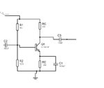
Here's the circuit so far:
amp.jpg

It was calculated for a IcQ=7.9057 [mA]. It also has a Zin = 2.058 [kΩ], Zout = 470 [Ω], AC voltage gain = -0.0678 ans Current gain of -2.8853.

According to the headphones' manufacturer, the impedance is 16 [Ω], and it has a sensitivity rate of 108 [dB/mW]. I've just tested it, and the microphone can't be heard. I have already tested them in the oscilloscope, so I haven't burned them.

My main question is, how do you determine how much current this circuit will need to feed the headphones, when the manufacturer info is quite obscure?

Best regards.
 

Your load of 16 Ohms is too low for your single-transistor amplifier. Its load is 470 Ohms as on the schematic, with your headphones it becomes ~12 Ohms only. This is why you have no audio gain.
You should use at least two transistor stages, and an output audio transformer for 470 to 16 Ohms impedance reduction.
Also, please use 12 kOhms instead of 2.2 k Ohms to feed Vcc to the electret microphone.

Since it's a project for class, I am restricted to only one transistor. I'll try to imcrease the microphone impedance and do the calculations for a higher load.

Thanks.
 

Since it's a project for class, I am restricted to only one transistor. I'll try to imcrease the microphone impedance and do the calculations for a higher load.

Thanks.

I am sorry about your class but this combination will not work.
Maybe you could force it into audio oscillation by putting the microphone close to the earphone.
A better option would be to find the old-style 2 kOhm headphones that can be used as the transistor load.
I would rather advise to use LM386, a good audio 1/2 Watt amplifier . You can load it even with a 4 to 8 Ohm loudspeaker, or with the microphone and 16 Ohm headphones you can add a long paper tube to the microphone and listen to people talking across the street.
Another option is to use a carbon microphone (from an old telephone) which offers a low-impedance and up to 9V audio output. Using an audio transformer for 470 to 16 Ohms at transistor output is, however, essential.

My question is: what you intend to teach your class by such misunderstood project?
 

I'm the student. It's about designing a single stage transistor amplifier, with the output from an electret microphone being the signal to amplify. It should be easy if I knew how much current is good for these headphones, but I can't find a clear explanation on the headphone parameters apart from the impedance. After picking the adequate current, it's just solving the system equations.
 

I'm the student. It's about designing a single stage transistor amplifier, with the output from an electret microphone being the signal to amplify. It should be easy if I knew how much current is good for these headphones, but I can't find a clear explanation on the headphone parameters apart from the impedance. After picking the adequate current, it's just solving the system equations.

I think your current of 5-10 mA is OK; if you find a 0.1V p-p audio signal source, you could hear the tone.

The problem is that your transistor amplifier needs 470-Ohm load to have a gain, so you need either a headphone with such or higher impedance, or, use a transformer as I described.
If you can use a FET like 2N7000, then you can adjust a higher gain at a DC current >10 mA, better to hear audio in your 16 Ohm headphones.
 

After picking the adequate current, it's just solving the system equations.

Here is a rough calculation:

Ic=7 mA >>> transconductance g=Ic/Vt=7/25 and 1/g=3.6.

Gain calculation: A=-RL/(1/g+RE) with RL=470||16=15.5 ohms.

This leads to A=-15.5/(3.6+100)=-0.15.

That means: No surprise because of a very small load resistance as well as signal feedback.
However, if you use a bypass capacitor across RE the gain will rise to A=-15.5/3.6=- 4.43

Is this sufficient?

It helps a bit. Now I can hear when I tap on it. Still, it doesn't pick the rest of the room noise.
 

Updating:

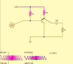
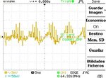
I got the waveform from my electret microphone, which is being polarized with 9 [V] and a 10 [kΩ] resistor.

This one was taken with ambient noise.
normal.jpg

This other was taken when I was speaking around it.
speaking.jpg

How can I simulate this behaviour in Proteus or similar?
 

Hi Sandthief

It was calculated for a IcQ=7.9057 [mA].
That allows a signal swing slightly more than 5mA RMS. Since the headphone impedance is much lower than the 470R collector resistor, most of that will go to the headphone.

According to the headphones' manufacturer, the impedance is 16 [Ω], and it has a sensitivity rate of 108 [dB/mW].....

My main question is, how do you determine how much current this circuit will need to feed the headphones, when the manufacturer info is quite obscure?
With a 16 Ohm load, the output power = I squared * R = 5mA*5mA*16R = 0.4mW. That's 4 decibels less than 1mW, so the maximum sound pressure level from the headphone will be 108 - 4 = 104dB. That's very loud.

So the maximum output is more than enough. Your only problem is not enough gain.

AC voltage gain = -0.0678 ans Current gain of -2.8853.
I've no idea how you worked that out but anyway.....

There's a few things you can do to improve it:

  1. Most important: As LvW pointed out, the 100 Ohm emitter resister is killing your gain. It needs to be bypassed with a capacitor from the emitter to ground. I suggest about 1000uF. Since the dynamic emitter impedance is about 4 Ohms, that will give a low frequency roll-off at about 40Hz. F = 1/(2*Pi*R*C)

  2. You need to increase C1 and C2 as well, otherwise you will hear some treble but no bass. 10uF for each would be OK. Again, F = 1/(2*Pi*R*C) or alternatively C = 1/(2*Pi*F*R).
    To do the calculation for C1, "R" = the series combination of the 470 Ohm collector resistor and the headphone i.e. about 500 Ohms. For the C2 calculation, R depends on the input impedance of the amplifier.

  3. If possible, use a BC547C. It has a higher current gain than BC547A or BC547B. See the datasheet for details.

  4. Cheat. If they're stereo headphones, connect the left and right channels in series, not in parallel. That way the total load on your amplifier is 32 Ohms instead of 8 Ohms. You get nearly double the gain.

How can I simulate this behavior in Proteus or similar?
It's easy to model the amplifier's behavior in a spice simulator. I don't know any wwwwa to model the microphone's behavior though.

Cheers - Godfrey

View attachment BC547.pdf
 
Last edited:
IF you are limited to a single transistor with the fewest parts....

Consider power gain as voltage gain and current gain. The mic has a FET current source whereby the voltage gain is determined by the load resistance at the expense of a higher supply voltage.

Then use your ONE transistor choice to a Darlington biased at a low voltage so that emitter DC losses are not too high and current can match the peak AC current into your headphones. Consider 1V into 32 Ohm emitter resistor with 1~2V on the emitter.
CC amp.jpg
Choose Base resistor so emitter voltage is ~1V below supply voltage to limit the power dissipation.

attempting to match impedance with current gain wins over voltage gain here due to the ratio in source to load impedance.

Just a rough design....
 
Last edited:

Thank you all for your responses.

I was doing the design wrongly, since I was fixing the DC conditions with values calculated for the AC part. We just discussed in class the effects of the capacitor in parallel with RE, and tomorrow we'll discuss how to design the amplifier for a particular load. I'll post how the amplifier goes. In the meantime, it's time to hit the books.

Cheers.
 

I was doing the design wrongly, since I was fixing the DC conditions with values calculated for the AC part.
I actually though your choice of DC conditions was very good. For example there's a decent amount of voltage across the emitter resister so the circuit won't be very sensitive to changes in temperature or battery voltage.

The worst kind of circuits are those that assume VBE = exactly 0.6V, HFE = exactly 100 or battery voltage = exactly 9V. All those are variable.
 

You haven't specified many important details, like what output power you want, and what the properties of the microphone are (like whether it has an internal preamp, what its sensitivity and output impedance are, etc). Without those you can't really make a smart design.

Do you know if you're allowed to use a darlington transistor? A lot of people would call a darlington one transistor...
 

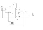
I redesigned it, using a load of 32 [Ω] and 1 [mW] of power. This time, I started from the AC load line, and calculated the resistor values.

apmv32.jpg

With this one, I realized that I live in a quite noisy environment. You can hear the microphone in a really quiet room, but not when people is playing music or talking too loud. According to this page (https://www.amazon.com/Sony-MDR-ED12LP-SLV-Earbuds-Silver/dp/B0015AM38Q
) the Power Handling Capacity is 100 [mW]. What does this value mean? Is it the maximum power the headphones can handle without burning? And what power would be a reasonable choice?
 

the Power Handling Capacity is 100 [mW]. What does this value mean? Is it the maximum power the headphones can handle without burning?
Yes.

And what power would be a reasonable choice?
The specs say "Sensitivity (db): 108 dB/mW" so 1mW will give you 108dB SPL, which is very loud.
0.01mW will give you 88dB SPL, enough for fairly loud music.
0.0001mW will give you 68dB SPL, which is a bit louder than normal speech.

As I said before, you have plenty of output power available. Your only problem is to get enough gain.
 

I managed to make it audible. According to my simulation, it receives .400 [mW] or so. I quickly built it this morning and I worked nicely. I just need to measure it in the lab and off to solder it. Thank you all for your attention.
 

Status
Not open for further replies.

Part and Inventory Search

Welcome to EDABoard.com

Sponsor

Back
Top