Welcome to our site! EDAboard.com is an international Electronics Discussion Forum focused on EDA software, circuits, schematics, books, theory, papers, asic, pld, 8051, DSP, Network, RF, Analog Design, PCB, Service Manuals... and a whole lot more! To participate you need to register. Registration is free. Click here to register now.
single supply 2 op-amp instrument amplifier with bi-polar input, is this possible? i keep reading that it is, then i simulate it and doesn't work. my input is +/- 50V, so that might be part of the issue.
You know that OPs have input voltage range specification.
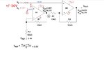
The presented circuit can work
- using appropriate voltage dividers as suggested by the sketched schematic
- connect the divider foot point to mid supply rather than ground
FvM - putting the reference on the divider worked, thanks! the resulting circuit has somehow a 50mV offset on the output, not sure where this is coming from.
I suppose I could use a 2.5V REF chip from analog devices for this?
feels super akward to offset the filter cap like this though.. i dunno, my gut feeling is to just use +/-5V supply to the opamps instead
do you think a divide by 500 (followed by a multiply by 10) as a first stage will be good if the input is only 2volts? to small a signal?
Not by design. Need to notice that unbalanced source resistance can generate an offset.
To achieve good common mode rejection, the voltage dividers must be well matched, e.g. 0.1 % for 60 dB CMRR. Differential amplifiers with built-in precision resistor networks like INA117 are hart to beat in this regard.
To decide about supply voltage range and OP selection, all application specifications must be considered.
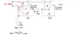
I would always tie the filter capacitors to signal ground, and filter the reference against ground, too.
ha, ya you're right. ok, revised. still, not convinced this will work.. also there's a reason i can not use the op-amp you selected, i need a single line out to the +/-50V. is strange, i know.
This site uses cookies to help personalise content, tailor your experience and to keep you logged in if you register.
By continuing to use this site, you are consenting to our use of cookies.

")