Continue to Site

Welcome to EDAboard.com

Welcome to our site! EDAboard.com is an international Electronics Discussion Forum focused on EDA software, circuits, schematics, books, theory, papers, asic, pld, 8051, DSP, Network, RF, Analog Design, PCB, Service Manuals... and a whole lot more! To participate you need to register. Registration is free. Click here to register now.

single phase inverter

Status
Not open for further replies.

noviceonrun11

Newbie level 4
Joined
Jul 15, 2011
Messages
6
Helped
0
Reputation
0
Reaction score
0
Trophy points
1,281
Activity points
1,331
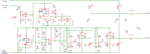
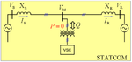
hello everyone i want to build a 12v to 20v pwm based voltage source inverter which would ultimately work as a static compensator. this static compensator would then be ultimately connected to the AC system of the nearly same magnitude. please help me with the circuit design as i'm getting nervous day by day...
 

Check out the WEBENCH designer on national.com. They have a nice tool that will help you design most any standard SMPS topology, and give you a good starting parts list. Plug in your voltage, current, and regulation requirements, and see what options you get. National makes SMPS controller IC's, so most of the comparators and PWM circuits are pre-packaged. I've used their tool(s) for several designs over the past 5 or so years.
 
  • Like
Reactions: ndukwe

    ndukwe

    Points: 2
    Helpful Answer Positive Rating
I assume, low voltage has been chosen for your project to allow a safe evaluation on a lab benchtop? Besides telling a voltage, pwm operation and the compensator objective, nothing has been said yet. You should e.g. have a block diagram that tells about the intended control flow and involved measurements. How do you want to implement the pwm circuit? Also some system parameters like pwm frequency, current, intended inverter topology (e.g. single phase H bridge) should be told. Do you intend displacement power factor compensation only, or also harmonic filtering?
 

For DC boost circuits are available on the net boostig to 19 volts to use laptop in car.
 

hello everyone.. my switching frequency is 2khz and i intend to run the circuit at 12V. how should i find the current flowing in the circuit... also without current i'm not able to calculate the power output of the circuit.. file 1 is the basic idea behind the whole project.. file 2 is the circuit i found on another electronic forum.. i built it up and tried to run it but could not get the desired output.. this circuit is for 300khz and i thought removing some resistors and capacitors might do the trick but that was not possible.. can anyone please suggest me the changes i can make to the circuit so that i can run it on 12V 2khz.. also after getting the output from this PWM VSI based inverter i need to connect it to a phase control IC so that i can synchronise AC side and inverter.. please help..
 

Attachments

  • 555 Full Bridge Signwave Power Inverter (dual volt input).png
    555 Full Bridge Signwave Power Inverter (dual volt input).png
    42.2 KB · Views: 109
  • idea.png
    idea.png
    42.8 KB · Views: 95

hello everyone.. my switching frequency is 2khz and i intend to run the circuit at 12V. how should i find the current flowing in the circuit... also without current i'm not able to calculate the power output of the circuit.. file 1 is the basic idea behind the whole project.. file 2 is the circuit i found on another electronic forum.. i built it up and tried to run it but could not get the desired output.. this circuit is for 300khz and i thought removing some resistors and capacitors might do the trick but that was not possible.. can anyone please suggest me the changes i can make to the circuit so that i can run it on 12V 2khz.. also after getting the output from this PWM VSI based inverter i need to connect it to a phase control IC so that i can synchronise AC side and inverter.. please help..

You can't simply remove resistors and caps to make a circuit put out more power. Those parts are there for a reason. So, how much power/voltage can the circuit you built deliver, and how much are you trying to get?
 

i'm supplying 12 volts dc to the circuit and want around 11 volts at the output.. based on the modulation index of 0.95 if i supply 12 volts i must get 11.4 volts at the output. please note that this is the spwm technique.. i want to built up a circuit for 2khz.. also can anyine give me some idea about the amount of current flowing in the circuit.. i tried to measure it in the lab but couldn't find any..
 

i'm supplying 12 volts dc to the circuit and want around 11 volts at the output..
11 V what? Vrms, Vpeak? If you can achieve 11 V peak (unlikely with IGBT switches, because they have about 1.5 to 2 V saturation voltage) you get 7.5 V sine rms.

i built it up and tried to run it but could not get the desired output..
Which problems do you observe. I assume, that the IR2113 isn't switching because is needs > 9V supply voltage.

this circuit is for 300khz
completely impossible with a 741 used as "comparator". The circuit may have problems even at 2 kHz , because no correct deadtimes are generated for the driver,

file 1 is the basic idea behind the whole project..
I got a basic idea about your intentions from the term "static compensator", but I have difficulties to recover it in the diagram

also after getting the output from this PWM VSI based inverter i need to connect it to a phase control IC so that i can synchronise AC side and inverter..
I suppose so. But honestly, I have no idea, how the 555 "sine" generator should work for it. Usually people have a PLL synchronized to the grid that's generating the sine reference. You would also need a voltage control loop to track variations of the grid voltage. Alternatively, the grid voltage, possibly bandpass filtered to remove harmonics, can be used as reference voltage. Variable phase shift and magnitude have to be applied.

The 1.5 - 3 uH seem a too low inductance to couple the inverter output to the grid.

Did you study any literatur about static compensators?
 

1) i want 11V peak to peak..
2) well nothing really.. it was just arial i reckon..
3) well thts wht (300KHz) it said in the associated litterature with the circuit.
4) the VSC shown in the diagram is the STATCOM... as u know it can be operated by VSC(voltage source converter) and CSC(current SC) topologies..
5) i'm not using 555 for phase synchronisation.. i'm thinking of using a phase controller circuit which would consist of a phase controller IC.. the reference triangular wave would be from the first IC555 U1 and inverter output would be the second reference..

All I'm trying to ask is what changes should i make to the above circuit so that it canwork for 12 volts 2 khz... or else can u please suggest me some other circuit which can be implemented for the above idea.. please help.. :)

---------- Post added at 12:58 ---------- Previous post was at 12:57 ----------

also can u guide me for the current in the circuit and the calculation of the leakage reactance of the coupling transformer which can be seen in the first basic diagram..
 

Status
Not open for further replies.

Similar threads

Part and Inventory Search

Welcome to EDABoard.com

Sponsor

Back
Top