rf1008
Full Member level 2
Recently,i was measuring balanced load's impedance,such as dipole antenna. I used Agilent E5061B VNA for the single-ended two-port measurement and got 4 S parameters,then the balanced impedance could be calculated by formula.
I found the result has much difference with simulation. One 75R 0603 resistor has been measured to verify the difference.S11=S22=0.429+j0,S12=S21=0.571+j0,they're the simulation data.But the measured results are:S11≈S22=0.423+j0.008,S12≈S21=0.511+j0.235. S11/S22 are quite similar ti simulation,S12/S21 have much difference in Real and Imag.
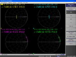
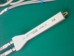
I finally found the doubt curve after VNA calibration,three pictures are attached here. N1021B is my single-ended two-port measurement fixture as differential probe. OPEN/SHORT/LOAD calibration is done at two coaxial ports and then use port extention function to compensate N1021B,the final calibration result is correct,pls refer to attachment which name is "calibrated". All actions above are correct,I think so!
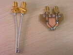
But when i shorted the two tips of N1021B,the curves of S12 and S21 changed much.In picture which name is "Tips short",you can find it.When two tips are short,S11 and S22 should be at 50 OHM point,S11=S22=0+j0,S12 and S21 should be at OPEN point,S12=S21=1+j0.The S11/S22 on Smith chart have a little variation from 0+j0 and can be accepted,S12/S21 however have too much variation from 1+j0, especially at 900MHz S12/S21=0.874+j0.483,the Real part is less then 1 and the Imag part is too much larger then j0.
I think the full calibration and compensation are correct, but, why S12/S21 changed too much according to OPEN point when N1021B two tips shorted togather. This instrument is purchased from Agilent this year, i don't think it has any problems.
Thanks,may someone could help me.
I found the result has much difference with simulation. One 75R 0603 resistor has been measured to verify the difference.S11=S22=0.429+j0,S12=S21=0.571+j0,they're the simulation data.But the measured results are:S11≈S22=0.423+j0.008,S12≈S21=0.511+j0.235. S11/S22 are quite similar ti simulation,S12/S21 have much difference in Real and Imag.
I finally found the doubt curve after VNA calibration,three pictures are attached here. N1021B is my single-ended two-port measurement fixture as differential probe. OPEN/SHORT/LOAD calibration is done at two coaxial ports and then use port extention function to compensate N1021B,the final calibration result is correct,pls refer to attachment which name is "calibrated". All actions above are correct,I think so!
But when i shorted the two tips of N1021B,the curves of S12 and S21 changed much.In picture which name is "Tips short",you can find it.When two tips are short,S11 and S22 should be at 50 OHM point,S11=S22=0+j0,S12 and S21 should be at OPEN point,S12=S21=1+j0.The S11/S22 on Smith chart have a little variation from 0+j0 and can be accepted,S12/S21 however have too much variation from 1+j0, especially at 900MHz S12/S21=0.874+j0.483,the Real part is less then 1 and the Imag part is too much larger then j0.
I think the full calibration and compensation are correct, but, why S12/S21 changed too much according to OPEN point when N1021B two tips shorted togather. This instrument is purchased from Agilent this year, i don't think it has any problems.
Thanks,may someone could help me.