Continue to Site

Welcome to EDAboard.com

Welcome to our site! EDAboard.com is an international Electronics Discussion Forum focused on EDA software, circuits, schematics, books, theory, papers, asic, pld, 8051, DSP, Network, RF, Analog Design, PCB, Service Manuals... and a whole lot more! To participate you need to register. Registration is free. Click here to register now.

[SOLVED] Single ended to differential signal conversion

Status
Not open for further replies.

countmybones

Junior Member level 3
Joined
Mar 11, 2005
Messages
30
Helped
2
Reputation
4
Reaction score
2
Trophy points
1,288
Visit site
Activity points
1,522
Hi all,

May I know why the following circuit output common mode voltage is not 0.9 V?
 

Attachments

  • single-ended_to_differential.zip
    665 bytes · Views: 153

you've got the 'signal' ( V1 ) connected to the wrong input ?

Edit: oh yes... i think your outputs are also flipped in the symbol. Check your + & -, and also your Inverting (with the 'o' symbol) & non-Inverting (w/o the 'o') output points.

checkout this example setup from their website -- (rename file to .asc)
View attachment LTC6406_DN454F03.txt
 
Last edited:
you've got the 'signal' ( V1 ) connected to the wrong input ?

Edit: oh yes... i think your outputs are also flipped in the symbol. Check your + & -, and also your Inverting (with the 'o' symbol) & non-Inverting (w/o the 'o') output points.

checkout this example setup from their website -- (rename file to .asc)
View attachment 85997
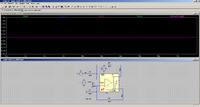
Thanks! That's it, the output with the 'o' symbol was swapped.
 

Status
Not open for further replies.

Part and Inventory Search

Welcome to EDABoard.com

Sponsor

Back
Top