peter_claybars
Newbie level 4
I have a dac that outpus a single ended signal (0-3.3v) which I need to convert into a differential signal. The differential signal needs to range from -6.6v to +6.6v (i.e. channel A ranges from -3.3v to +3.3v and channel B ranges from -3.3v to +3.3v). Channel A and Channel B are centered around "GND" which in this case is 0v of the DAC
When the dac outputs 1.65v (the middle of the range) I wanted the differential output to be zero. When the dac outputs 0 or 3.3v, I wanted the range to be -6.6v or +6.6v.
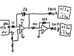
I built a circuit to accomplish this using two inverting op-amps where the first amplifies the signal with a gain of 2 and the second inverting op-amp is of unity gain.
Because I wanted 1.65v to equate to 0v differential output, I connected the "+" of the first op-amp to +9v via a pot
After building this circuit, I found it didn't work. I couldn't get 1.65v to result in 0v output and the min/max range values were not symmetrical around 0v.
After some research, I found this was due to the "voltage offset" characteristic of op-amps which for the op-amp I am using (tl074) is 3000uV!
I know I can get 5uV or less op-amps, but I was wondering if there is a better solution. The lower voltage offset op-amps will probably be ok for me, but I would really prefer a solution that I can "tune" once, then for about, even if the device's temperature fluctuates +/-10 degrees C.
Any help would be appreciated!
When the dac outputs 1.65v (the middle of the range) I wanted the differential output to be zero. When the dac outputs 0 or 3.3v, I wanted the range to be -6.6v or +6.6v.
I built a circuit to accomplish this using two inverting op-amps where the first amplifies the signal with a gain of 2 and the second inverting op-amp is of unity gain.
Because I wanted 1.65v to equate to 0v differential output, I connected the "+" of the first op-amp to +9v via a pot
After building this circuit, I found it didn't work. I couldn't get 1.65v to result in 0v output and the min/max range values were not symmetrical around 0v.
After some research, I found this was due to the "voltage offset" characteristic of op-amps which for the op-amp I am using (tl074) is 3000uV!
I know I can get 5uV or less op-amps, but I was wondering if there is a better solution. The lower voltage offset op-amps will probably be ok for me, but I would really prefer a solution that I can "tune" once, then for about, even if the device's temperature fluctuates +/-10 degrees C.
Any help would be appreciated!
")