Continue to Site

Welcome to EDAboard.com

Welcome to our site! EDAboard.com is an international Electronics Discussion Forum focused on EDA software, circuits, schematics, books, theory, papers, asic, pld, 8051, DSP, Network, RF, Analog Design, PCB, Service Manuals... and a whole lot more! To participate you need to register. Registration is free. Click here to register now.

sine to square conversion using pic16f877 c adc program with ccs

Status
Not open for further replies.

mepramo

Newbie level 3
Joined
Jan 5, 2011
Messages
3
Helped
0
Reputation
0
Reaction score
0
Trophy points
1,281
Activity points
1,303
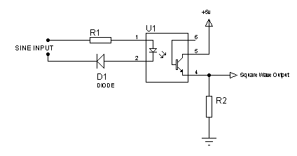
I am doing a project where i need to find the frequency of a waveform generated by a spark plug. I am using pic 16f 877a & ccs compiler for programming. As a beginning am trying to assume that the wavform to be measured is a sine. And convert it into an adc and make it square, & find the frequency.i am beginner in this field and am nt able to programme it.
 

Hi,
Try with something like this for sine to square conversion:

79_1294204053.png


Then you can try with this algorithm:
1. Wait for zero-crossing.
2. When zero-crossing occurs, start timer.
3. Wait for next zero-crossing.
4. When zero-crossing occurs, stop timer.
5. Load timer value into a register.
6. Start timer again.
7. Calculate how much time the timer value corresponds to.
8. Find frequency by using F=1/T

Hope this helps.
Tahmid.
 
One more thing ..
I need also to find pulse width too.. can you thow some light on that
 

Hi,
Study the capture module (CCP) section in the datasheet thoroughly. You can use capture module for pulse width measurement. There are other ways very similar to the algorithm I showed above. If your input is sine, then you can use the time measured through the above algorithm as the pulse width.

Hope this helps.
Tahmid.
 

One more thing ..
I need also to find pulse width too.. can you thow some light on that

This sounds more like a pulse-detection problem than a periodic sine wave. In that case, here is the approach I'd take. (I'd first put an oscilloscope probe on the signal you are detecting, so you know what it looks like, and what characteristics you can use to determine the "start" and "end"... only then you can build the software to "look" for those characteristics.

1. Monitor the ADC for the rising-edge of waveform (a while loop?). You'll have to pick a threshold, maybe 1/2 the peak amplitude of the pulse?... something a fair amount greater than the noise level on the ADC input.
2. When the rising edge is detected, start two timers.
3. When the falling edge of the waveform is detected, stop timer1 (this will represent the pulse-width).
4. When next rising edge hits, stop timer2. This will be equal to the pulse interval. As Tahmid said, use F = 1/t to calculate the PRF (pulse-repetition frequency).
5. Reset and wait for next rising edge.

This method would let you sample and evaluate every other pulse. If you modify the algorithm, you could use more than two timers (or shotgun the aforementioned two timers), so you can pick up every pulse. If you get really inventive, you could drop some of this code into an interrupt service routine (ISR) to handle the timer set/load/resets. The sky is the limit.
 

Our aim is :

1.We want to monitor the frequency of the signal which controls the timing of spark plug. Do anyone know from where to tap this anonymous signal and shape and V,I ranges? As it need not be sine wave we think about an external comparator(op-amp) to generate square.

2. And then we have to find the dwell angle. Is it vary in current generation bikes (we have to do the work in BIKES). And whether the pulse width of previously generated square wave will give the dwell angle?

3.We need a sensor to monitor the exhaust CO content from vehicle. We find many of them in web. But could not find a particular one which may suit.
 

Status
Not open for further replies.

Similar threads

Part and Inventory Search

Welcome to EDABoard.com

Sponsor

Back
Top