heryrg
Junior Member level 1
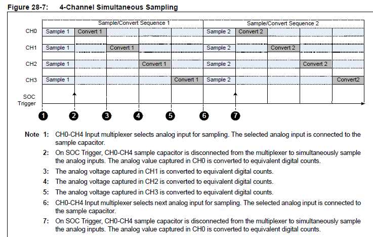
Hello friends. I have a question for you all. I'm working on a little project where i need to keep track of 4 analog inputs. I'm using dsPic33fj to simultaneously sample these 4 inputs. See the image bellow for illustration of what i want to do. My question is: can i manually save each conversion after it is done without using DMA? So after step3 save convert1 then after step4 save convert2 and so on.
Ultimately i do not want to use DMA but will if i really have to. I would like to use ADC1 Interrupt after each conversion but even if i specify 1 conversion between interrupts, the interrupt does not get triggered after each conversion. Below is the ADC initialization, ADC interrupt, and DMA initialization.
I know i probably left some details out, so please be kind to ask me questions or let me know if you need more info. Also, please if you could please let me know if i setup my DMA buffers correct.
ADC Initialization:
DMA Initialization:
ADC1 Interrupt:
Ultimately i do not want to use DMA but will if i really have to. I would like to use ADC1 Interrupt after each conversion but even if i specify 1 conversion between interrupts, the interrupt does not get triggered after each conversion. Below is the ADC initialization, ADC interrupt, and DMA initialization.
I know i probably left some details out, so please be kind to ask me questions or let me know if you need more info. Also, please if you could please let me know if i setup my DMA buffers correct.
ADC Initialization:
Code:
void initAdc1(void)
{

AD1CON1bits.ADON = 0;
AD1CON1bits.AD12B = 0; // Select 10-bit mode 1=12bit
AD1CON2bits.CHPS = 3; // Select 4-channel mode
AD1CON1bits.SIMSAM = 1; // Enable Simultaneous Sampling
AD1CON1bits.ADDMABM = 1; // DMA buffer written in order of conversion
AD1CON2bits.ALTS = 1; // Enable Alternate Input Selection
AD1CON2bits.SMPI = 1; // Select 1 conversion between interrupt
AD1CON1bits.ASAM = 1; // Enable Automatic Sampling 0=SAMP must be set before sampling
AD1CON1bits.SSRC = 2; // Timer3 generates SOC trigger
AD1CON2bits.CSCNA = 0; // No input scan

//	AD1CON3bits.ADRC=0;			// ADC Clock is derived from Systems Clock
//	AD1CON3bits.ADCS = 63;		// ADC Conversion Clock Tad=Tcy*(ADCS+1)= (1/40M)*64 = 1.6us (625Khz)

// Initialize MUXA Input Selection
AD1CHS0bits.CH0SA = 8; // Select AN8 for CH0 +ve input
AD1CHS0bits.CH0NA = 0; // Select VREF- for CH0 -ve input
AD1CHS123bits.CH123SA = 0; // Select CH1 +ve = AN0, CH2 +ve = AN1, CH3 +ve = AN2
AD1CHS123bits.CH123NA = 0; // Select VREF- for CH1/CH2/CH3 -ve inputs

// Initialize MUXB Input Selection
AD1CHS0bits.CH0SB = 11; // Select AN11 for CH0 +ve input
AD1CHS0bits.CH0NB = 0; // Select VREF- for CH0 -ve input
AD1CHS123bits.CH123SB = 1; // Select CH1 +ve = AN3, CH2 +ve = AN4, CH3 +ve = AN5

IPC3bits.AD1IP = 7;			// Set Priority to highest level 7
IFS0bits.AD1IF = 0;			// Clear the A/D interrupt flag bit
IEC0bits.AD1IE = 1;			// Enable A/D interrupt
AD1CON1bits.ADON = 1;


}
DMA Initialization:
Code:
#define  MAX_CHNUM	 			13		// Highest Analog input number in Channel Scan
#define  SAMP_BUFF_SIZE	 		8		// Size of the input buffer per analog input
#define  NUM_CHS2SCAN			4		// Number of channels enabled for channel scan


// Number of locations for ADC buffer = 14 (AN0 to AN13) x 8 = 112 words
// Align the buffer to 128 words or 256 bytes. This is needed for peripheral indirect mode
int  BufferA[MAX_CHNUM+1][SAMP_BUFF_SIZE] __attribute__((space(dma),aligned(256)));
int  BufferB[MAX_CHNUM+1][SAMP_BUFF_SIZE] __attribute__((space(dma),aligned(256)));

void initDma0(void)
{
	DMA0CONbits.AMODE = 2;			// Configure DMA for Peripheral indirect mode
	DMA0CONbits.MODE  = 2;			// Configure DMA for Continuous Ping-Pong mode

	DMA0CNT = (SAMP_BUFF_SIZE*NUM_CHS2SCAN)-1;
	DMA0REQ = 13;					// Select ADC1 as DMA Request source

	DMA0STA = __builtin_dmaoffset(BufferA);
	DMA0STB = __builtin_dmaoffset(BufferB);

	IFS0bits.DMA0IF = 0;			//Clear the DMA interrupt flag bit
    IEC0bits.DMA0IE = 1;			//Set the DMA interrupt enable bit

	DMA0CONbits.CHEN=1;


}
ADC1 Interrupt:
Code:
void __attribute__((interrupt, no_auto_psv)) _ADC1Interrupt(void)
{

		if (y < 127)
		{
  		array[y] = ADC1BUF0; //  get ADC value
		LATE = array[y];       // Display the data
		y++;
		}
		else y=0;

		IFS0bits.AD1IF = 0;			// Clear the A/D interrupt flag bit

}