Continue to Site

Welcome to EDAboard.com

Welcome to our site! EDAboard.com is an international Electronics Discussion Forum focused on EDA software, circuits, schematics, books, theory, papers, asic, pld, 8051, DSP, Network, RF, Analog Design, PCB, Service Manuals... and a whole lot more! To participate you need to register. Registration is free. Click here to register now.

[PIC] Simulation problem (gray squares )

Status
Not open for further replies.

SABRAMANSOUR

Junior Member level 2
Joined
Dec 16, 2014
Messages
23
Helped
0
Reputation
0
Reaction score
0
Trophy points
1
Visit site
Activity points
127
what's the problem with the gray squares at the pins of PORTB, C, D, E that's my project please help me it's urgent
:cry: :cry: :cry:
111111.png
Code:
void main(){
unsigned int v0,v1,v2,v3,v5;
ADC_Init();  // Initialize ADC module with default set
//CMCON = 0x07; // Disable comparators
ADCON0 = 0x00; // Select ADC channel AN0
ADCON1 = 0x0F; // RA0 as analog input
TRISC = 0x00;
PORTC= 0 ;
PORTA= 0xFF ;
TRISA = 0xFF;
 PORTB= 0 ;
TRISB = 0x00;
 PORTE= 0 ;
TRISE = 0x00;
  PORTD= 0 ;
TRISD = 0x00;

INTCON = 0  ;

  do {

   ADCON0=0b11000101;     // Configure chanal 0

     delay_us(500);
   v0 = ADC_Read(0);   // Get 10-bit results of AD conversion
    delay_us(500);

    ADCON0=0b11001101;     // Configure chanal 1
       delay_us(500);
    v1 = ADC_Read(1);   // Get 10-bit results of AD conversion

    delay_us(500);

    ADCON0=0b11100101;      // Configure chanal 4
      delay_us(500);
    v5 = ADC_Read(5);   // Get 10-bit results of AD conversion
      delay_us(500);
    if ((v0>v5)||(v1>v5));
       {if (v0>v1)                       //  comparaison  des tensions  des capteurs LDR1 et LDR2 si v0>v1
          {
           PORTB.f0=1;             // pour tourné le moteur dans le sens 1 la sortie de pic RB0==1 et RB1==0
           PORTB.f1=0;    // PORTB.1=0;
           delay_us(500);
          }
       else                              // sinon
          {
           PORTB.f0=0;             // pour tourné le moteur dans le sens 1 la sortie de pic RB0==0 et RB1==1
           PORTB.f1=1;    // PORTB.1=0;
           delay_us(500);
          }
       }
    if ((v0<v5)&&(v1<v5));
          {
           PORTB.f0=0;             // pour tourné le moteur dans le sens 1 la sortie de pic RB0==1 et RB1==0
           PORTB.f1=0;    // PORTB.1=0;
           delay_us(500);
          }
     //SENS VERTICALE;

     ADCON0=0b11010101;     // Configure chanal 2
    delay_us(500);
    v2 = ADC_Read(2);   // Get 10-bit results of AD conversion
    delay_us(500);


    ADCON0=0b11011101;     // Configure chanal 3
     delay_us(500);
    v3 = ADC_Read(3);   // Get 10-bit results of AD conversion
     delay_us(500);


    ADCON0=0b11100101;      // Configure chanal 4
     delay_us(500);
    v5 = ADC_Read(5);   // Get 10-bit results of AD conversion
     delay_us(500);

      if ((v2>v5)||(v3>v5));
       {if (v2>v3)                       //  comparaison  des tensions  des capteurs LDR2 et LDR3 si v2>v3
          {
           PORTB.f2=1;             // pour tourné le moteur dans le sens 1 la sortie de pic RB2==1 et RB3==0
           PORTB.f3=0;
           delay_us(500);
          }
       else                              // sinon
          {
           PORTB.f2=0;             // pour tourné le moteur dans le sens 1 la sortie de pic RB0==0 et RB1==1
           PORTB.f3=1;    // PORTB.1=0;
           delay_us(500);
          }
       }
       if ((v2<v5)&(v3<v5));
          {
           PORTB.f2=0;             // pour tourné le moteur dans le sens 1 la sortie de pic RB2==0 et RB3==1
           PORTB.f3=0;
           delay_us(500);
          }

  } while(1);
}
 

Look's like your program even not start. Possible, because MCLR pin used in configuration and connected nowhere. Use pull up resistor at least. For simulation only you can connect MCLR pin to VCC directly. Proteus doesn't simulate startup reset pulse, crystal oscillator, coffe machines and e.t.c. It using SPICE engine whith some primitive microcontrollers options.
 

well i used the pull up resistor but the problem doesn't solved
I didn't understant what do you mean by " using SPICE engine whith some primitive microcontrollers options."
 

"Grey" designates unknown state, e.g. floating input. If it's observed with pins that should be initialized as outputs, it means that the code isn't executed regulary. To see why, you can load a *.cof instead of *.hex file and trace program execution in Proteus source level debugger.

Although I won't contradict the Proteus qualification by Easyreader83 as "SPICE engine whith some primitive microcontrollers options", even this primitive options can be helpful if used intelligently.
 

Binary file 1.hex is missing, you should also attach the debug binary 1.cof to allow code debuuging.
 

Zip and attach the complete mikroC project. We need to see the configurations you have set.
 
Last edited:

What are all the semi colons (;) after while(1) and if() conditions ? Proteus 8.1 file attached. Proteus file has been modified.
 

Attachments

  • project_3.rar
    47.7 KB · Views: 116
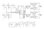
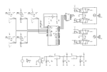
There are several errors in the schematic!!!
The diode bridge is connected wrongly, the 12V supply shorted to 5V (all is named as VSS???), the relay coils are without power of 12V, the ULN2003 connected wrongly, etc...

These are my suggestions for the schematic (Proteus 7.10SP0):

Project_4.png

Using only one ULN2003A:

Project_4-B.png
 

Attachments

  • Project_4.zip
    158.5 KB · Views: 117
Last edited:
thank you so much
that's my first project it wasnt easy for me
I make stupid mistakes and I'm happy tha I found this forum thanksfor all whoes help me specially " nagkiller "
 

Status
Not open for further replies.

Similar threads

Part and Inventory Search

Welcome to EDABoard.com

Sponsor

Back
Top