Continue to Site

Welcome to EDAboard.com

Welcome to our site! EDAboard.com is an international Electronics Discussion Forum focused on EDA software, circuits, schematics, books, theory, papers, asic, pld, 8051, DSP, Network, RF, Analog Design, PCB, Service Manuals... and a whole lot more! To participate you need to register. Registration is free. Click here to register now.

Simulation of LOAD TRANSIENT ANALYSIS OF LDO

Status
Not open for further replies.

tompham

Full Member level 2
Joined
May 29, 2010
Messages
133
Helped
29
Reputation
60
Reaction score
29
Trophy points
1,308
Location
usa
Activity points
2,066
Hi all

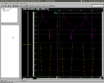
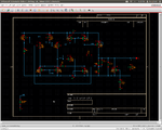
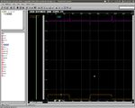
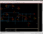
I am designing LDO using tsmc 180nm, VDD=1.8v, Vout=1.6v (200mV drop out). I have trouble running load transient response.

If I connect output to a voltage source to generate load current (see attached file) the output transient very good. If I connect output

to current source the spike up and down are quite huge (~400mV). Could anyone tell me which is correct way to run it. Thanks a lot.
 

Attachments

  • Screenshot at 2012-09-19 21:25:20.png
    Screenshot at 2012-09-19 21:25:20.png
    42.3 KB · Views: 130
  • Screenshot at 2012-09-19 21:25:53.png
    Screenshot at 2012-09-19 21:25:53.png
    62.7 KB · Views: 121

The usual test uses a resistive load that is switched in and out. Typically you have a fixed resistive load and switch another resistor in and out to generate a certain percentage change in the load (perhaps 10% to 20% or more).

A current load could also be used as a worst-case test.

A voltage load does not work since a voltage source has zero impedance and thus the output is forced to the value of the source, independent of anything the regulator does. Thus the transient response will look very good since you are looking at the transient response of the voltage source.
 

Hi crutschow

Thanks for reply me. I use a resistive load test as attached file but the spike is around 100mV. I try to reduce to 50mV but not easy task.
Do you have any idea to improve it? My ground current is 10uA at VDD=1.8v. Thanks
 

Attachments

  • Screenshot at 2012-09-20 00:43:36.png
    Screenshot at 2012-09-20 00:43:36.png
    43.4 KB · Views: 109
  • Screenshot at 2012-09-20 00:44:13.png
    Screenshot at 2012-09-20 00:44:13.png
    57.2 KB · Views: 104

Status
Not open for further replies.

Similar threads

Part and Inventory Search

Welcome to EDABoard.com

Sponsor

Back
Top