Continue to Site

Welcome to EDAboard.com

Welcome to our site! EDAboard.com is an international Electronics Discussion Forum focused on EDA software, circuits, schematics, books, theory, papers, asic, pld, 8051, DSP, Network, RF, Analog Design, PCB, Service Manuals... and a whole lot more! To participate you need to register. Registration is free. Click here to register now.

Simulating a 13.56MHz RFID Antenna in CST. How should I proceed?

Status
Not open for further replies.

mtcolaco

Newbie
Joined
Feb 4, 2022
Messages
4
Helped
0
Reputation
0
Reaction score
0
Trophy points
1
Activity points
45
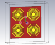
Hello there I'm having quite a lot of trouble simulating a simple project in CST Studio Suite, emulating the antenna from the following paper ((PDF) Design and simulation of 13.56 MHz RFID tag in ink-jet printing technology (researchgate.net)): I used copper as a ground (0.035mm), paper as the substrate (0.68mm) and PEC as the conductive(0.). I have assigned a Time Domain Solver and used an RCS probe with no decent results (attached below).

Capturar.JPG
2.JPG


How should I proceed? If I were to use the Frequency Domain solver, how should I do it?

I have also attached the project file, if anyone wants to take a closer look.
 

Attachments

  • RFID_CardV1.zip
    79.6 KB · Views: 127

Copper as ground can't work, it shorts the magnetic coil.

13.56 MHz coupler coil can be treated as AC magnetic problem + some coil self capacitance due to small dimensions compared to wavelength.
 

I have removed the ground and sunk the conductor a bit into the substrate. Unfortunately, the results have not changed much.

1644516096944.png
1644516113474.png


I don't understand the idea behind using a rcs probe for testing the RFID coil.

The test setup in the linked paper has a resonance capacitor and measuring a radiation pattern, apparently with an E-field sensor.
 

First of all, thank you for your responses!

To be completely frank, I'm quite new to CST and electromagnetic simulation in general. The RCS probe was a simulation setup I got from a previous RFID project I got working (although it used closed loop resonators - I attached a picture below). I tried using Discrete Ports previously as well with no decent results. I've been trying to simulate an E-Field (f=0.01356 GHz, with a field probe at z=20mm), and I got the following results:

1644540019456.png
1644540039864.png
1644540743354.png

The radiation pattern seems to be identical:

1644540391107.png

I should clarify here that my objective is to simply obtain the S parameters of the tag. Should I add ports to the tag? If so what kind and where (I know this might be obvious but the placement of ports at the spiral ends has gotten me some warnings/errors in the past)?
 

Attachments

  • 1644538200078.png
    1644538200078.png
    51.9 KB · Views: 113
  • RFID_CardV2.zip
    105.5 KB · Views: 121

Status
Not open for further replies.

Similar threads

Part and Inventory Search

Welcome to EDABoard.com

Sponsor

Back
Top