carter tsang
Newbie level 6
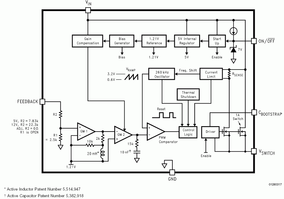
lm2674 inductor
because the real indcutor can be replaced by the simulated inductor, which consists of op-amps, resistors and capacitors, can I use the simulated inductor to substitute the real inductor in the dc-dc converter, such as buck or buck-boost circuit?
need some suggestions!
thank you very much!
because the real indcutor can be replaced by the simulated inductor, which consists of op-amps, resistors and capacitors, can I use the simulated inductor to substitute the real inductor in the dc-dc converter, such as buck or buck-boost circuit?
need some suggestions!
thank you very much!
 sorry, I do not know how to conduct