peterpops
Junior Member level 3
Hello!
Another question regarding a problem in Microelectronic circuits 5th ed by Sedra Smith (exercise 1.20)
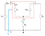
Please see the attached image. Everything except the green arrow and label is in the original figure

Problem:
Find the input resistance between terminals B and G in the circuit shown in the attached image. The voltage vx is a test voltage with the input resistance Rin defined as Rin = vx / ix
My approach
ix = ib
the currents sum in the point above E in the figure is
ix + βix - ie = 0
EQ 1: ix = ie / (1 + β)
ie = ve / Re
ve = vx * (Re / (Re + rπ))
ie = vx / (Re + rπ)
inserted into EQ 1
ix = (vx / (Re + rπ)) / (1 + β) = vx / ((Re + rπ)*(1 + β))
And finally
Rin = vx/ix = (Re + rπ)*(1 + β)
However
Answer by the book is Rin = rπ + (β + 1)Re
So I have one "βrπ" to much.. what's wrong with my calculations??
Another question regarding a problem in Microelectronic circuits 5th ed by Sedra Smith (exercise 1.20)
Please see the attached image. Everything except the green arrow and label is in the original figure

Problem:
Find the input resistance between terminals B and G in the circuit shown in the attached image. The voltage vx is a test voltage with the input resistance Rin defined as Rin = vx / ix
My approach
ix = ib
the currents sum in the point above E in the figure is
ix + βix - ie = 0
EQ 1: ix = ie / (1 + β)
ie = ve / Re
ve = vx * (Re / (Re + rπ))
ie = vx / (Re + rπ)
inserted into EQ 1
ix = (vx / (Re + rπ)) / (1 + β) = vx / ((Re + rπ)*(1 + β))
And finally
Rin = vx/ix = (Re + rπ)*(1 + β)
However
Answer by the book is Rin = rπ + (β + 1)Re
So I have one "βrπ" to much.. what's wrong with my calculations??