Continue to Site

Welcome to EDAboard.com

Welcome to our site! EDAboard.com is an international Electronics Discussion Forum focused on EDA software, circuits, schematics, books, theory, papers, asic, pld, 8051, DSP, Network, RF, Analog Design, PCB, Service Manuals... and a whole lot more! To participate you need to register. Registration is free. Click here to register now.

simple short distance transmission of audio signals using IR rays

Status
Not open for further replies.

rajaram04

Advanced Member level 3
Joined
Jun 17, 2012
Messages
871
Helped
6
Reputation
12
Reaction score
5
Trophy points
1,298
Location
earth
Activity points
7,687
Hello sir,
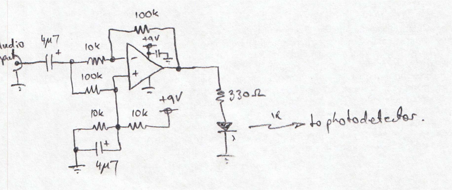
I want to make a wireless audio transmission circuit , Not with very much components but need a simple n easy one to get the motive
I have my audio signals ready to fed-in so need no audio transformer or something like that
Already i ve seen some headphone circuits its getting to expensive n too complicated.I don't want that i need simplest one . . please help
thanks
 

Video demonstration of what you want to do:

https://www.youtube.com/watch?v=n0f7blVJIIg&feature=related

Summary of a simple project:

You add a DC component to the audio signal, then send it to an IR emitter led. It's an audio-modulated IR beam.

The beam is picked up by an IR photodetector, fed into an amplifier which detects the audio riding the DC, then to your headphones or audio system.

The following project uses IR pulses, and provides better audio quality:

www.instructables.com/id/DIY-Infrared-transmitter-for-iPhone-iPod/

A past thread at this board discusses IR transmitting. Related threads are listed at the bottom of the linked webpage.

https://www.edaboard.com/threads/67804/
 

Heya rajaram - here's a simple circuit that does exactly as Brad describes: impresses an (amplified) audio signal on a DC bias and directly modulates a LED:


There are many suitable photodetector designs to use as the receiver out there - an old post of mine that should work for you:

Good luck :)
 
woww sir thanks all of you i ll try from basic to all the attempt hoping a best to my work :) thanks

- - - Updated - - -

thylacine1975 sir u ve posted here the transmitter circuit , now what about its detector unit ? please explain :) thankss
 

The attached .pdf of post #3 describes a suitable detector circuit. While I originally wrote the document as an aid to people making general purpose optics labs detectors, it's quite suitable for your application. With a single op-amp and a few other components, it's about as simple as it gets too! It's nothing special though - just a "textbook" photodiode transimpedance amplifier - and there are plenty of other (better) solutions out there... such as those listed by Brad (in post #10) of this thread: https://www.edaboard.com/threads/229306/.

Don't forget to capacitively couple the output of the photodetector to your audio amplifier, to prevent the DC output component from causing your amplifier grief!
 

thanks thanks thanks a lot sir its enough to pull me for the period of a month to make several experiments , wow it is brilliant all i got here . . sir here in the circuit diagram you gave me has a capacitor at input , is the polarity o.k. here ??? please check & confirm it to me please . . the figure is below

79_1342597955.jpg

- - - Updated - - -

which op amp i may use here in this circuit ? 741 or any thing else ? please comment . . thanks
 

Aye - the capacitor polarity is correct... the op-amp inputs are biased to mid-rail (~4.5 V) by the 10K/10K voltage divider, and hence the capacitor has its' positive terminal connected to the op-amp.

The op-amp needs to be able to source the LED current, which for the values shown could approach: (9Vrail - 2V LED Vf)/330R ~= 21 mA. (Un)fortunately this is beyond the (horrible) 741, so you'll need an op-amp with greater output capability and (preferably) rail-rail output swing for maximum IR signal amplitude. Bandwidth is unimportant, so anything that can operate from 9V (also expressed as +/- 5V), source 25 mA and swing close to the rails will probably do - parts that spring to mind are: AD8055, LM6361, MAX4392 etc etc. Any op-amp rated for service as a 'buffer' or 'video driver' would be a likely candidate.

Cheers :)


ya sir i got that

here for your transmitter circuit i found a reciever unit , so would it work or what changes i ve to make ? please tell

2009616235424928.gif
 

The audio circuit in the post #8 will not work:
1) The 741 opamp needs its (+) input biased at half the supply voltage so its output can swing up AND DOWN with the audio signal. Its output needs to be capacitor-coupled to the volume control.
2) The LM386 power amp is missing the important series RC to ground at its output and an important supply decoupling capacitor, all shown on its datasheet.


ohh then lots of missing things & circuit is totally incomplete specially in absence of series RC

- - - Updated - - -

well ok sir then how to design a proper audio transmitter & receiver section via infrared signals ?
i need it for a very very short distance . .
 

well ok sir then how to design a proper audio transmitter & receiver section via infrared signals?
First you must learn about the basics of electronics.
Then you must learn about how opamp circuits work.
Then you must learn about how to read the datasheet of an IC like the LM386 little power amplifier.
 

First you must learn about the basics of electronics.
Then you must learn about how opamp circuits work.
Then you must learn about how to read the datasheet of an IC like the LM386 little power amplifier.


i read already but when coming to practice it all goes either way with what i read in basic electronics
well coming to the point please please help me in designing what i need here

i can too make trials but risk of heavy damages are there . .

seriously speaking if i need to study for basic electronics then you are the best teacher to me or if i try then again same npn pnp forward reverse bias pn junction .7 volts nothing more than that . .

but if you explain then only i come to know what actually a chapter tells . . . sp please help
 

Sorry. I am not a teacher. I like talking about complicated circuits with people who know about complicated circuits.
Somebody on this forum might teach you.
 

Sorry. I am not a teacher. I like talking about complicated circuits with people who know about complicated circuits.
Somebody on this forum might teach you.


okk done , then please help me in solving matters for circuits posted above . . please


Too sir i want to tell something that in so many threads i got some circuits with complications & components but i made experiments last years on the basis , i removed related components & supplies by making circuits compact & less power consuming just on the basis of your explanations , all are working nicely

for a very short term example for some opamp circuit i was told once to connect non inverting input to ground via 100k resistor or something like that then only any theory ll proceed , ya agree but i wondered that it was obstacle to me & i ve to left that terminal as N.C. & still that circuit is working properly & its in front of me now , just i need to show my palm to the sensor at a distance of 75 cm from me , its working well even on a weak used battery . .

credit all goes to you here cause you told me some basic about bread board about static electricity etc etc & all that

now hope you may understand
 
Last edited:

Status
Not open for further replies.

Part and Inventory Search

Welcome to EDABoard.com

Sponsor

Back
Top