neazoi
Advanced Member level 6
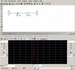
Hi I use rfsim99 and I have found very good and symmetrical response when simulating a single series LC from input to output. By adjusting the values, I can also get very sharp responses at various frequencies.
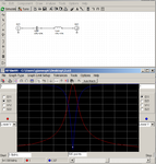
I could just not get these sharp responses using a parallel shunt LC.
I know the question is a bit general but, are these characteristics generally realistic for a series LC or am I doing something wrong?
I could just not get these sharp responses using a parallel shunt LC.
I know the question is a bit general but, are these characteristics generally realistic for a series LC or am I doing something wrong?