Continue to Site

Welcome to EDAboard.com

Welcome to our site! EDAboard.com is an international Electronics Discussion Forum focused on EDA software, circuits, schematics, books, theory, papers, asic, pld, 8051, DSP, Network, RF, Analog Design, PCB, Service Manuals... and a whole lot more! To participate you need to register. Registration is free. Click here to register now.

Simple Question About Diode Mixer

Status
Not open for further replies.

EEPC

Newbie level 6
Joined
Oct 8, 2010
Messages
14
Helped
0
Reputation
0
Reaction score
0
Trophy points
1,281
Activity points
1,459
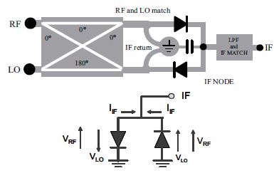
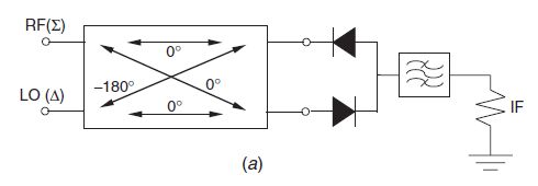
Hi all, I have a quick question about how a single-balanced diode mixer works. Here is a picture of the circuit:

8_1336885716.jpg


Suppose the RF voltage has amplitude Vrf and LO signal has amplitude Vlo, and there is a RF bypass to ground at the node between the two diodes. Then the amplitude of voltage at the left terminal of the top diode is (Vrf - Vlo) while the voltage at the left terminal of the bottom diode is (Vrf + Vlo), right?

I don't really understand how current flows out of the IF node, because it seems that two diodes in series will just conduct current in one direction only (and zero current will flow into the IF branch).

Can anyone help explain to me precisely how this circuit works? Thanks!
 

You have to remember that Vrf and Vlo amplitudes are only the max amplitudes. Mixers do their job on the frequencies involved. You have to visualise what happens when RF freq is (say) 10 Mhz and LO freq is (say) 2Mhz sine waves & then see what happens at each instant as the 2 voltages vary.
 

Thanks rohitkhanna, I found another picture (taken from a paper) to better explain my question:

50_1336897557.jpg


The reasoning here is that since the diodes are reversed (and LO is out of phase), the small-signal IF currents i(t) = g(t)*v(t) add in phase at the IF node, where g(t) is the diode conductance and v(t) is RF signal. Perhaps I just don't understand diodes well enough, but how is it that the current is flowing "up" from the left diode shown? So diodes only oppose the flow of DC current in that direction, but a small-signal current can still flow that way?
 

The key point to realize is that for a diode mixer to operate properly, the LO must be much larger than the RF (at least 20 dB), and ideally much larger than the turn on voltage of the diodes. If this is true, then as a simplification consider the diodes to be ideal switches that are controlled solely by the amplitude of the LO. The time domain waveform at the IF is the RF signal multiplied by 0 or 1 depending on the state of the switches (which are switching at the LO frequency). It is a "chopped" version of the incident RF waveform. This produces the sum and difference frequencies, RF feedthrough, and a host of other harmonics. The IF filter then rejects all but the desired IF (upper or lower sideband). LO feedthrough at least is is not an issue in an ideal SBM, although it is there at a low level when actual components are used.
 
Status
Not open for further replies.

Part and Inventory Search

Welcome to EDABoard.com

Sponsor

Back
Top