Continue to Site

Welcome to EDAboard.com

Welcome to our site! EDAboard.com is an international Electronics Discussion Forum focused on EDA software, circuits, schematics, books, theory, papers, asic, pld, 8051, DSP, Network, RF, Analog Design, PCB, Service Manuals... and a whole lot more! To participate you need to register. Registration is free. Click here to register now.

Simple Diode Circuit for half wave rectification

Status
Not open for further replies.

yellowmania

Junior Member level 1
Joined
Feb 2, 2012
Messages
16
Helped
0
Reputation
0
Reaction score
0
Trophy points
1,281
Activity points
1,407
I have a circuit with a 12V AC supply adapter frequency of 50Hz, one diode and a 100K Load Resistor all in series. i have measured the voltage with a multimeter set to DC across the load resistor to be 5.8 Volts but i'm rusty on the theory as to why i have gained this value. As the supply is 12V and the wave is half rectified is it simply a case of half waveform half voltage? or is there more to it, Any Ideas would be helpful!
 
Last edited:
yellowmania said:
I have a circuit with a 12V AC supply adapter frequency of 50Hz, one diode and a 100K Load Resistor all in series. i have measured the voltage across the load resistor to be 5.8 Volts
5.8V on the resistor leaves another 6.2V on the diode which doesn't make sence. Can you measure the voltage drop on the diode?
 
with the sheets i was following i wasnt asked to, it said measure across RL and comment on the reading obtained. have changed the post above, Would measuring with a multimeter set to DC provide a reasonable conclusion or is it still not making sense, then no problem and thank you for replying!
 

The multimeter SHOULD be set to DC but there is a catch.... what the meter reads will depend upon the type of meter. What you are seeing is an 'average' of half wave rectified AC, in other words half sine cycles with gaps between them so the reading is lower than expected. Some meters will give different readings though, depending on how quickly they sample the voltage. For example, the mass of the needle and coil in an analog meter will make it show the average voltage but a DVM will take periodic samples of the waveform and may read zero if it samples at the missing half cycle or peak voltage if it samples at the top of the half sine. So with a DVM you might see almost random readings.

Brian.
 
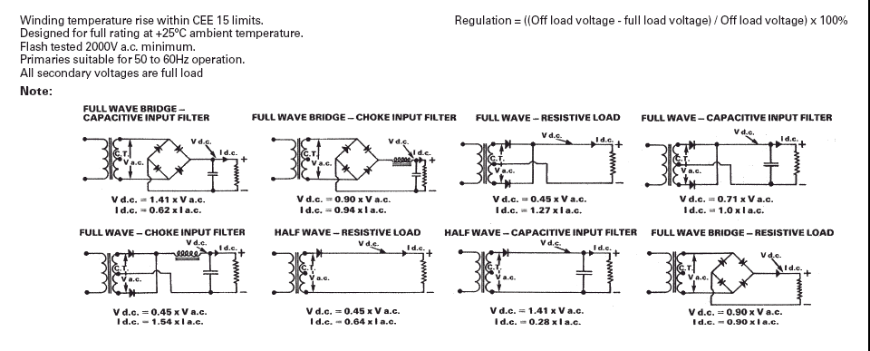
yellowmania, your result sounds about right. See the second circuit on the bottom line.


rects.gif
 
Status
Not open for further replies.

Similar threads

Part and Inventory Search

Welcome to EDABoard.com

Sponsor

Back
Top