Continue to Site

Welcome to EDAboard.com

Welcome to our site! EDAboard.com is an international Electronics Discussion Forum focused on EDA software, circuits, schematics, books, theory, papers, asic, pld, 8051, DSP, Network, RF, Analog Design, PCB, Service Manuals... and a whole lot more! To participate you need to register. Registration is free. Click here to register now.

SIM900 TXD and RXD Voltage Question Please Help

Status
Not open for further replies.

Jacob Harris

Newbie level 6
Joined
Dec 4, 2014
Messages
11
Helped
2
Reputation
4
Reaction score
2
Trophy points
3
Activity points
110
I am looking to use the SIM900 module. I see that the module's power supply is from 3.2 V to 4.8 V. I will be running it with an ATMEGA328P microprocessor who's power supply range is from 1.8 V to 5 V. Naturally I would like to choose a power supply between 3.2 V to 4.8 V and simply use one power supply.

If this works that would be simplest. The question comes in when I see that the SIM900's RXD port needs to be pulled up to VDD_EXT externally. Which is at 2.8 Volts. Does that mean that serial communication can only work at 2.8 volts and that I cannot use a serial communication at 3.2 to 4.8 volts? I would like to know before I send data through at 4 V and destroy the SIM900.

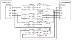
I have seen some level shifter schematics which sound like it would work but I would like to avoid that complexity if possible. If I had to use a level shifter that would mean that I would be using two different power supplies and that would not be optimum. See the attached.

Here is the SIM900 datasheet if needed. **broken link removed**
 

Attachments

  • serial interface.jpg
    serial interface.jpg
    83.6 KB · Views: 149

The question comes in when I see that the SIM900's RXD port needs to be pulled up to VDD_EXT externally. Which is at 2.8 Volts

Where is this condition mentioned?

Does that mean that serial communication can only work at 2.8 volts and that I cannot use a serial communication at 3.2 to 4.8 volts? I would like to know before I send data through at 4 V and destroy the SIM900.

You can use resistor divider in between uC TX pin and RX pin of GSM Module to work around 2.8v to 3.1v (abs max V). But TX pin of GSM Module and RX pin of uC can be connected directly.

pmk

- - - Updated - - -

ABS MAX VOLT - attached
 

Attachments

  • AbsMax_DigiPin_SIM900.gif
    AbsMax_DigiPin_SIM900.gif
    10.8 KB · Views: 145
Where is this condition mentioned?

- - - Updated - - -

ABS MAX VOLT - attached

I have attached a snip of all the places I found it was mentioned. I am not sure why it specifies this condition.
My questions about it are:
1. Does this mean that transmission from uC to Sim900 needs to be at 2.8V or can it be at something nicer for me like 3.3V?
2. Do I really need to pull it up externally?

You can use resistor divider in between uC TX pin and RX pin of GSM Module to work around 2.8v to 3.1v (abs max V). But TX pin of GSM Module and RX pin of uC can be connected directly.

- - - Updated - - -

ABS MAX VOLT - attached

Assuming that you say that the 2.8 V is needed from the above questions a voltage divider sounds like a really easy way to get the 2.8 V. I have three questions with that then.
1 Assuming pulling it up to 2.8 V is needed, how would I still use the voltage divider? (I have an attached idea).
2 Should I be concerned about the size of resistors I use in the divider? I would hate to use something too big and limit it too much. (this may not be a concern because it is a data port.)
3. Why did you say "3.1v (abs max V)" I saw that there was supposed to be an attachment but I didn't see it. Also 3.1 is below the sim900 voltage limit. Why not 3.3 or 4VCapture6.PNGCapture7.PNG?

- - - Updated - - -

speedEC,

For some reason your attachment just come through for me. I understand now why you said 3.1 V is the MAX now and why shooting for 2.8 V isn't such a bad idea. I would also assume that I should choose the resistance in my voltage divider to limit my current to under 10mA seeing how I input* is 10ma from your attachment. I do still have that question about if why and how the RXD pin needs to be pulled up to VDD_EXT?
 

if why and how the RXD pin needs to be pulled up to VDD_EXT?

No need to pull up RXD pin of GSM Module to VDD or VDD_EXT? Who told you to do this? As I already said, you can use resistor divider between uC TX pin and GSM Module's RXD pin. Short the pins of RTS & CTS of GSM Module or left open. Usually users only use RXD & TXD pins of GSM Module and left all other pins open.

hope this help.
pmk

- - - Updated - - -

just now I checked the datasheet that you provided. You should pull-up RXD pin of SIM900 to VDD_EXT through pullup resistor. I am using SIM900B. Such connection does not required in SIM900B module. Hope you can get some help from other user on this issue regarding this issue.

I have also little bit confusing on this issue. It will be cumbersome to use resistor divider on RXD pin.

refer and send pvt msg to the user or google SIM900 circuit in edaboard forum:
https://www.edaboard.com/threads/231838/

pmk
 

Just connect the SIM900 TXD to the MCU UART input pin and the SIM900 RXD to the MCU UART output pin via a resistor divider.

That's all you need to do.

Cheers.

SIM900_Serial.jpg
 
  • Like
Reactions: inlog

    inlog

    Points: 2
    Helpful Answer Positive Rating
Status
Not open for further replies.

Similar threads

Part and Inventory Search

Welcome to EDABoard.com

Sponsor

Back
Top