moyoumin
Junior Member level 2
- Joined
- Oct 13, 2009
- Messages
- 23
- Helped
- 9
- Reputation
- 18
- Reaction score
- 9
- Trophy points
- 1,283
- Location
- Shenzhen,China
- Activity points
- 1,411
Hi, at present, SIM908 don't support FOTA.
Follow along with the video below to see how to install our site as a web app on your home screen.
Note: This feature may not be available in some browsers.


Hi cnd,
I'm not an experienced or expert using SIM900, but when I started with this module I had some issues, so I could give you some ideas.
a) SIM card not inserted issue. You should start checking the sim card interface in this order.
a.1) Check that the SIM900 pin number and sim card socket pins are the correct and right connected. (Design problem)
a.2) Check that VDD 220nF-100nF capacitor is mounted on the board. (Mounting problem)
a.3) Check that 22nF capacitor of SIMDATA is also mounted on the board. (Mounting problem)
a.4) Check that there is a short between the SIM900 pins and the sim card connector pins with a tester. (Soldering problem)
If all of the above items are checked and ok I don't know what could be happenning. Maybe another more experienced thread poster can help you...
b) Programming issue. Check the same process but using 115200bps instead of 1152000bps. This could be the reason why programming is falling.
Regards,
Ignacio
- - - Updated - - -
Hi,
...I know that there is another thread available, but maybe this is more readed than the other one...
Has anyone of the exprecienced SIM900 users fixed or solved the issue that there is no option for auto powering-up the module when is supplied with a supply voltage?...
Isn't there any hardware or software solution aside using a small microcontroller for generate the powerkey signal after module power-up process?...
regards,
Ignacio


About the issue to control auto power up and your proposed solution, this is exactly what I don't want to do. I don't want to use an microcontroller to only startup the module once it is powered. I want that SIM900 powers up and starts running just after I connect power to the VBAT, and not after making the pwrkey sequence.
regards,
Ignacio
")
Hello everyone,
Firstly, thank-you for the SIM900 dialog above. It has proven helpful to me.
I currently have a SIM900 ver 1137B07 firmware. The module is from Open electronics. I have a number of Arduino shield versions of the SIM900 as well.
Unfortunately I have written my code to take advantage of features in 1137B09 (not sure, 1137B08 may work as well) but unfortunately I can't update the FW in the Openelectronics module.
I have done this FW upgrade a few time on the Arduino shields without problems.
The Openelectronics module has an off-module TTL logic level converter - 2.8 to 5V & Im using an FT232 to run the module via USB. I have tried both main & debug ports on the module plus a wide range of baud rates (max 115200, min 9600).
Serial dialog with the module is ok. The FW upgrade fails a few seconds after module power-up, with a "Frame Error 12" (Im recounting this from memory, it may be frame error 10). Im using firmware loader v1.01. I see there is a new version - V1.10 but it does not appear to have a SIM900 option.
Does anyone have any suggestions to help resolve this?
Many thanks,
Refsmmat
Hello der.
Pls give some screen shot images of ur error report. it will make thing easier to get.
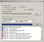
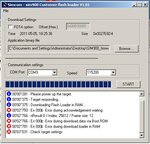
Thanks for the reply. Two images are attached. Using AT+IPR Ive tried the upgrade with the module baud rate set to 9600 & 115200 before the upgrade. I have read the module switches to 115200 when the bootloader is active.
I had not correctly reported the errors in my previous post. Per the images, case 1 (SIM900 set to 9600, Cust flash loader 9600) the error is Error 306. Case 2 (SIM900 set to 115200, Cust flash loader 115200) the error is Error 000.
Regards,
refsmmat
Hi Refsmmat
You have to make sure that the pwrkey is shorted to ground throughout the entirety of the update process. I can't say for sure but this looks similar to the errors I used to get when I released the pwrkey too early (it was a long time ago).
HELLO refsmmat
it looks like we both are having exactly same error report while flashing the module. Check my post#247 in this thread I have also mentioned same error report. i am actually trying to fix this for last few days. I have tried almost all possible ways to debug it, but still no good result. in addition my module even does not detecting the SIM inserted.
Oky you can try one more thing which I today discovered in my circuit. As i m using full handshaking UART mode with FT232R and SIM900. I found that I made an mistake while designing the board layout i.e I just wrongly connect RTS & CTS lines from FT232 with SIM900. it just got swapped. I have made dis corrected in new design layout, but it will take me a week to get new board n test it. So as u mentioned on previous post that u are using FT232 for UART communication, so pls check if ur using theses two line correctly(if u r using FULL HANDSHAKING UART MODE). If u r using standard TTL UART (i.e RX, TX, GND) Then i dont think it will work to flash as i Hv already tried this on my module. I wud advice u to go for FULL handshaking UART mode.
Regards
CND
- - - Updated - - -
Yah I have also experienced it.
benhaham
* I did several upgrades and as experience I can tell you the best way or at least that I do not give less errors is the option 460800 baud with the flash loader V1.01
with 460800 i got 'Error during change baud rate'
any way else?