Continue to Site

Welcome to EDAboard.com

Welcome to our site! EDAboard.com is an international Electronics Discussion Forum focused on EDA software, circuits, schematics, books, theory, papers, asic, pld, 8051, DSP, Network, RF, Analog Design, PCB, Service Manuals... and a whole lot more! To participate you need to register. Registration is free. Click here to register now.

Sim900 auto-Power down after network registration

Status
Not open for further replies.
Thank you for snapping me out of it. Btw, I found on alibaba a 100uF 0603 MLCC for about $0.1 If I order 25, do you think that its too good to be true, someone told me it is, and I think it might be, but I am just hoping.... https://szgoldtech.en.alibaba.com/p...9/orginal_SMD_capacitors_100uf_6_3V_0603.html
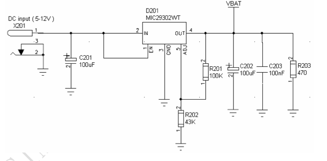
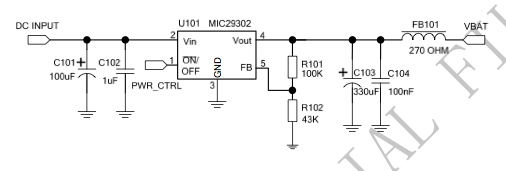
I just read an article in one of the trade journals about counterfeit capacitors. You wouldn't think that it would be worth the effort, but some companies are removing caps from recycled electronics and selling them as new. In some cases the are remarking them to indicate they are a different value than they actually are. I'd be leary of anything that is too cheap.

Btw what is the reason you buy your caps from Taiyo Yuden instead of TDK the first one listed, like an ignorant person like me might do? I know (as you could tell) nothing about corporations, but I have learned so much more now just in these few posts.
I don't usually prefer one manufacturer over another for passive components. That cap was the first in the search I did looking for a 100uF, MLCC, 6.3V, XR7 dielectric sorted by price.
 
  • Like
Reactions: msj121

    msj121

    Points: 2
    Helpful Answer Positive Rating
I see, yes sorting by price makes sense. I have decided to avoid Alibaba, too good to be true indeed.

I have also decided, though I might try to solder the current board, I will likely make a new revision as I have been finding a couple of mistakes. Sadly it was already ordered, but I am excited to see whether the board physically is a good representation of my eagle file.

Two more questions now that I am redesigning the board.

1). Can I use the MLCC 100uF 1206 for the VRTc. I notice in the design notes it says to use a tantalum cap. If this is better, I will probably just use the recommended tantalum and mlcc as originally suggested, even for the Power pin.
2). I originally to keep things simple was going to take the LiOn battery straight to the board etc... I wanted to use as few elements as possible to preserve power, Should I just use the recommended circuit in the design notes? It looks like it is for a battery more than 5 volts though to regulate it to 4.1 V. Will this same circuit work if the batter is already a 3.7 Volt battery or 4 Volt battery? If I do use a 5+V battery, is the power loss inherent probably too large to make this worthwhile if I will use a solar power charger for the battery.

Thank you for your help so far. I figure the last question might be too complicated to expect an answer, but I do appreciate any effort or knowledge you might have.

Finally, I noticed after studying all the design notes again and again after our conversations, finally understanding quite a bit more. There is a change for the transistor to pwr_key, whether to have a 1kohm resistor between the transistor and the pin. The newest design not I have (v 2.00) does not contain the 1kohm resistor. Should I simply follow the latest design note? I would assume so.
 

1). Can I use the MLCC 100uF 1206 for the VRTc. I notice in the design notes it says to use a tantalum cap. If this is better, I will probably just use the recommended tantalum and mlcc as originally suggested, even for the Power pin.
Actually, the "Reference Design Guide" recommends a 4.7uF ceramic cap.

2). I originally to keep things simple was going to take the LiOn battery straight to the board etc... I wanted to use as few elements as possible to preserve power, Should I just use the recommended circuit in the design notes? It looks like it is for a battery more than 5 volts though to regulate it to 4.1 V. Will this same circuit work if the batter is already a 3.7 Volt battery or 4 Volt battery? If I do use a 5+V battery, is the power loss inherent probably too large to make this worthwhile if I will use a solar power charger for the battery.
If you are running the SIM900 from a Li-Ion battery you should connect the battery directly to the module. You only need a regulator if your supply voltage is above 4.7 volts. If your supply voltage is below 3.6V you would need a "boost regulator" to increase the voltage. However, I don't recommend it, as that type of regulator does not work well for this application. Charging a Li-Ion battery while it's connected to the SIM900 is no simple feat. If you are goiing to use solar to charge the battery the best approach is to use something like a 6V Gel Cell battery with a linear regulator. The charger circuit will be much simpler.

There is a change for the transistor to pwr_key, whether to have a 1kohm resistor between the transistor and the pin. The newest design not I have (v 2.00) does not contain the 1kohm resistor. Should I simply follow the latest design note? I would assume so.
Yes, follow the latest design note.
 
  • Like
Reactions: msj121

    msj121

    Points: 2
    Helpful Answer Positive Rating
Actually, the "Reference Design Guide" recommends a 4.7uF ceramic cap.

Impressive, it seems that is mentioned in the pin description but not the schematic (just a drawing no values). Instead of the hardware reference design I checked the PCB and Layout design note and there it was mentioned beside the schematic. I guess I should start being much more careful each time through and double check the other design notes, not just one or two. I suppose then that the 100 tantalum is safer so I will stick with that since you recommended it. In that case if I am using one tantalum cap, I might as well use two and protect vbat properly with a tantalum cap and an mlcc as you suggested originally.

If you are running the SIM900 from a Li-Ion battery you should connect the battery directly to the module. You only need a regulator if your supply voltage is above 4.7 volts. If your supply voltage is below 3.6V you would need a "boost regulator" to increase the voltage. However, I don't recommend it, as that type of regulator does not work well for this application. Charging a Li-Ion battery while it's connected to the SIM900 is no simple feat. If you are goiing to use solar to charge the battery the best approach is to use something like a 6V Gel Cell battery with a linear regulator. The charger circuit will be much simpler.

I will follow your advice about the regulator, back to Eagle, with sadness and excitement. I suppose I am lucky I didn't build the circuit only ordered a couple of pcbs.
 

So I am now designing the regulator, quick questions:
1). The ferrite bead (FB101) is only necessary if I have a DC-DC converter (LM2596) - source (PCB Layout Schematic & Reference).
2). C103 (330uF) and C104 (1uF) are right after the power regulator. Are these the new decoupling capacitors right beside VBat instead of 100uF and 0.01uF I was told to use before? Or do I need all 4?
3). I will probably keep the power on, is there a way to keep the mic29302 on, without a switch? I did a google search, but kept finding odd pdfs.
4). Should I spend the extra money for 470uF (it mentions that a 500mA source from USB should use such a high capacitor). The reason I ask is because I need to program a micro that will share the vbat, that means when I power the circuit from USB to program the micro, the sim900 would likely suddenly turn off, I have no idea how this will affect the micro programming, but might sap the power, I am a little scared it will steal the power from the micro and also shut down the micro not letting me program it.
5). For the decoupling capacitor right before the vbat with the ldo, does the esr need to still be less than 150mOhm? Is 150 fine, or should i get 125 or 100?
Any advice as I design this stage of the pcb?

Thank you again!
 

Typically the micro-controller and SIM900 are supplied through separate regulators as their supply voltages are usually different. I generally use a LDO regulator like Microchip MCP182x. If the regulator is close to the Vbat pin you don't need the extra caps. A standard USB port can not provide enough current to power the SIM900.
 
  • Like
Reactions: msj121

    msj121

    Points: 2
    Helpful Answer Positive Rating
I would like to use one ldo for both, to reduce cost and size.... The manual (PCB layout design note) says to use a 470nF to use USB, not sure if that is only for the voltage converter not the regulator though.... I will buy a 470nF anyway, maybe it will work. I really really want to use one power source for both....


I solved "3)" the ldo, I tied the on off to power, I think that is what will keep it active.
 

As I am just finishing the schematic design, I notice that you told me 0.01uF beside Vbat, and the schematic for their power source would like me to put 0.1uF (100nF) beside vbat. Should I just go with 0.1uf or 1uf better safe than sorry? In fact can I just replace the other 0.1uF (beside the simcard, and beside reset) to 1uF (that way I only am using 1uF in the design), or is 0.1uF sometimes better than 1uF (all of the above would be MLCC).

Also the schematic power source has two different designs, sometimes vbat has a 470ohm resistor going to ground and sometimes not, is the difference whether to put a ferrite bead or 470 ohm resistor? Very confused at the moment.
 

You can use either a .01uF or .1uF cap for that - both will do the trick.

It's difficult to comment on SIMCom's power supply designs, as I don't know what their design criteria was. Ferrite beads are very effective at isolating high frequency noise generated by either the power supply or the device. You may want to refer this Micrel's design notes for that regulator. Also, a good treatise on power supply filtering can be found here: https://www.ti.com/lit/an/scaa048/scaa048.pdf
 

Hello everyone!
I am developing board with sim900d and I've got one problem. I am able to turn on STATUS light but NETLIGHT is still OFF, 0V on PIN. I am using power supply from Vbat, Li-on battery 4.1V and Vcharg -> 5V 2A. I designed board according to DS but I still can't figure out how to make my modem to log into network? Please, help me :)

Edit.
Ok, it seems that module is working anyway. I can call it, and when the call is being held pin RI is brought to 0V. But still, I don't know why netlight is off
 
Last edited:

Here it is: schemat_gsm.png
 

Your connections look fine. Are you sure you don't have a short between that pin and something else?
 

I'm pretty sure everything is fine. I even broke broke a connection so that there would be a pin alone.
 

I am having some problem with my SIM900D, at first its got connected to the network but now it does not connects to the network. I check the AT+CREG command and the result is +CREG:1,3 3 means registration denied. I have this same problem with my old module then I changed the SIM900D SMD it worked fine with my interfacing board. Something is wrong with SIM900D. I have tested the module in other working interfacing board but still it is not connecting to the network. Please help me out :((
I am having a similar problem. I purchased an EFCom GPRS shield (Arduino compatible) from elec freaks:
**broken link removed**
I had it connected and working, able to send and receive text messages up until yesterday. Yesterday when I shut down and restarted the device, it was unable to register in the network. I configured it to send me network registration result codes (AT+CREG=1) and found that registration was being denied (+CREG=3). I don't understand why it is not working because it was working just fine the day before. Any ideas why network registration would be denied? I've tried about everything I can think of to find and/or fix the problem, including calling my mobile provider to verify that the IMEI is not blacklisted (It isn't). This project is for a Christmas present, so a timely response would be greatly appreciated. Thanks!
 

Are you sure that you can connect to a cell tower for your service provider? Can you move your device to another location and try it there?
 

Ok, I tried it again and during searching I got +CSQ=0,0 and then registration rejection again and still +CSQ=0,0 for a little bit, then after a short while it registered, signal strength was +CSQ=9,0. I'm not sure why it started working because yesterday and the day before I tried various places with a range of signal strengths ranging from +CSQ=5,0 or so to +CSQ=14,0 and it wasn't registering then. The +CSQ=14,0 was in direct line of sight to the tower and it still wasn't registering. Any ideas of what could have caused that? I'm afraid to shut the module down because I might not be able to re-register on the network.
 

You can compute the Received Signal Strength in dBm using the formula: level = 113 - (value * 2); where value is the value returned by the AT+CSQ command. This will always produce a negative level with the lowest level being -113dBm; the closer to zero the level is the stronger the signal. The levels you observed are:
Code:
5 = -103 dBm
9 =  -95 dBm
14 = -85 dBm

While there is no official conversion from dBm to signal bars, I use the following values in my products. They don't correlate to the number of bars displayed on any given phone, but are a reasonable visual indicator:
Code:
-113 to -110 = 0 bars
-109 to -101 = 1 bar
-102 to -91 = 2 bars
-92 to -85 = 3 bars
-86 to -76 = 4 bars
 > -76 = 5 bars

You should be able to register with a signal level above -110 dBm IF the signal is from a cell of your service provider, or one that has a roaming agreement with your provider. Are you sure the tower you are near is one of your service provider's towers?
 
I called AT&T and they said the tower is theirs. I have AT&T for both my phone and this SIM900 board. My cell phone says I have 4 bars and no problems, I've even swapped sim cards with the SIM900 and both cards work fine. Is there possible larger gains in the cell phone that the SIM900 shield is having problems, but the cell phone isn't? What other problems could there be? I'm having trouble again registering on the network. Right now I have a signal strength of +CSQ: 7,0 = -99dBm according to your formula. Also, is it normal to get +CSQ: 0,0 while the device is trying to register?
 

No it's not normal to have a CSQ of 0 when registering - you'll never register with that level. However, if the signal level is -99 dBm with a 0 BER the issue isn't the signal level. Try sending the command "AT+CENG=1,1" and then the command "AT+CENG?". That will return Engineering Data that contains info on all of the cells the radio finds.
 

Status
Not open for further replies.

Part and Inventory Search

Welcome to EDABoard.com

Sponsor

Back
Top