Continue to Site

Welcome to EDAboard.com

Welcome to our site! EDAboard.com is an international Electronics Discussion Forum focused on EDA software, circuits, schematics, books, theory, papers, asic, pld, 8051, DSP, Network, RF, Analog Design, PCB, Service Manuals... and a whole lot more! To participate you need to register. Registration is free. Click here to register now.

Signal strength for 5V signal over 20meter

Status
Not open for further replies.

Bjtpower_magic

Full Member level 1
Joined
May 28, 2020
Messages
98
Helped
0
Reputation
0
Reaction score
0
Trophy points
6
Activity points
876
Hello Everyone,

I need your help to understand explanation on below.

wire distance.PNG


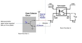
Optocoupler-We are using detector (Diode) stage here
Transistor switch will on when we give commands so it is not continuous frequency signal.

Black (Bottom)- is common GND for Switch and Optocoupler

What are the probable reason i need to look into for wire selection? if i use shielded cable then where i can connect or keep it open>

Marx
 

The answer depends on how quickly you are switching the transistor on and off. If the optocoupler is just sensing dark or a continuous light source you can use almost any cable as long as it doesn't pass through a very high interference zone. If it switches rapidly or carries data you may have to take into account the properties of the cable, in particular the capacitance between inner wire and shield because it may slow down the rise and fall of the signal edges.

Brian.
 
Hi,

there are many different optocouplers, there are many different transistors, there are many different circuits.
We don´t know what´s hidden inside the blue boxes.
So...with all this unknown...how can we help?

Wire selection according:
* expected voltage drop (also depends on circuit)
* expected timing and waveform (also depends on circuit)
* impedance controlled signaling? (... circuit)
* possible sources of noise
* coupling of noise (capacitive, magnetic)
* noise frequency
* noise immunity of circuit (.. circuit)

*****
If you need more details, then please show a schematic with standard symbols. Hand drawn is O.K.

Klaus
 

The answer depends on how quickly you are switching the transistor on and off. If the optocoupler is just sensing dark or a continuous light source you can use almost any cable as long as it doesn't pass through a very high interference zone. If it switches rapidly or carries data you may have to take into account the properties of the cable, in particular the capacitance between inner wire and shield because it may slow down the rise and fall of the signal edges.

Brian.
Hi Brian,
Thanks for reply.

We are switching Transistor when we want to and it needs user intervention.
I would like to more understand on Shield connections.

i was thinking twisted pair cable with shielding but i dont know where i can connect shield.

Can you guide more on it?
 

Hi,

there are many different optocouplers, there are many different transistors, there are many different circuits.
We don´t know what´s hidden inside the blue boxes.
So...with all this unknown...how can we help?

Wire selection according:
* expected voltage drop (also depends on circuit)
* expected timing and waveform (also depends on circuit)
* impedance controlled signaling? (... circuit)
* possible sources of noise
* coupling of noise (capacitive, magnetic)
* noise frequency
* noise immunity of circuit (.. circuit)

*****
If you need more details, then please show a schematic with standard symbols. Hand drawn is O.K.

Klaus
Hi Klaus,

Please find the schematics
Optocoupler-TLP 271 and BJT (Any general purpose)

Optocoupler circuitry is another room and BJT Switching circuitry is in different room.
Distance between them is 20meter.
--- Updated ---

Hi Klaus,

Please find the schematics
Optocoupler-TLP 271 and BJT (Any general purpose)

Optocoupler circuitry is another room and BJT Switching circuitry is in different room.
Distance between them is 20meter.
Power supply is different for both only GND of both is shorted
--- Updated ---

Interface.jpg

Please find the schematics
Optocoupler-TLP 271 and BJT (Any general purpose)

Optocoupler circuitry is another room and BJT Switching circuitry is in different room.
Distance between them is 20meter.

power supply is different for both only GND is common (We have shorted with Wire)
 

Attachments

  • Interface.jpg
    Interface.jpg
    80.6 KB · Views: 90

Hi,

Now it makes much more sense.
Now signal flow is from left to right, which is correct.

Optocoupler: It´s not the detector side, but light emitter (LED) side.
Are you sure the part name is TLP-271? Give a link to the datasheet.

I´d use a shielded cable. even better if it includes twisted pairs.
Good available is a ethernet cable. CAT5 or better.

Any other is good, too.

In any case: * I recommend to use two Zeners (something 5.1V ... 12V). One on each side from the according GND (A) to the switching signal (K). This should be some kind of ESD protection. (Better than nothing). Do this before you connect anything else.
* don´t use an extra wire to short GND between both circuits. Use the cable below. Otherwise you risk GND loop problems.

If a shielded cable with twisted pair:
* connect the shield on one side only to GND. Maybe one circuit GND is connected to EARTH_GND, then use this one. If not, don´t care.
* always connect one wire of the pair on both sides to the according GND. Don´t leave the GND unconnected. (in your schematic I see a dashed line)
* connect the other wire of the pair with the switched signal
* no problem if other pairs remain unconnected.

If a coax is used (single wire shielded):
* always connect the shield on both sides to the according GND. Don´t leave the GND unconnected. (in your schematic I see a dashed line)
* connect the center wire with the switched signal

Don´t use very thin wires (no thin microphone cable).

Klaus
 
Hi Klaus,
Optocoupler part is TLP291 not TLP271

In Shielded or Co-axial cable- GND loop is certain (GND will be moved 20meter).

How shield actually work here?
Dotted Line is just representation but it is actual wires.

If i used 2 core shield wire then wiring look like this.
1)Shield- Where to connect???
2)Red-Sw signal or open collector to R1
3) Black-GND of Open collector transitor GND to Optocoupler GND

I have 2 pin connector at both end

Marx
 

Connect the shield to the GND at one end or use it as the second wire so you only need one wire to carry the signal. In other words use it instead of the black wire and then you only need a single wire (the core of the shielded cable) to use as the red wire.

Brian.
 
For future consideration there is always wireless or fiber, both full duplex capable,
costs pretty low these days. ESP8266 for wireless, TOS for fiber -

**broken link removed**

Numerous advantages over Cu links.


Regards, Dana.
 

Hi,
Can twisted Pair cable will work?
I don't know how i connect shield in connector, any idea.
I have 3.8mm phoenix mkdsn series connectors
 

Hi,

I have already written: Connect on one side shield to GND. That´s it.

Klaus
 

Twisted pair -


I think because your data rate quite low your primary concern is noise rejection and Cu losses affecting noise margin,
which you would have to calculate.


Regards, Dana.
 
Status
Not open for further replies.

Similar threads

Part and Inventory Search

Welcome to EDABoard.com

Sponsor

Back
Top