Continue to Site

Welcome to EDAboard.com

Welcome to our site! EDAboard.com is an international Electronics Discussion Forum focused on EDA software, circuits, schematics, books, theory, papers, asic, pld, 8051, DSP, Network, RF, Analog Design, PCB, Service Manuals... and a whole lot more! To participate you need to register. Registration is free. Click here to register now.

Signal Integrity Problem with DDR2 SDRAM and DSP in Altium - Top Signal Level value

Status
Not open for further replies.

neopisha

Junior Member level 2
Joined
Nov 30, 2011
Messages
23
Helped
2
Reputation
4
Reaction score
2
Trophy points
1,283
Activity points
1,440
Hi, I am trying to analysis Signal Integrity for a DDR2 SDRAM and OMAPL138 in Altium. There is a problem with signal levels. I've set the Signal Top Value rule to 1.8V for desired nets but in the simulation the default 5V top level signal is injecting. How can I change this value to 1.8V?
I've tried Signal Top Value and Base Value rules and I've edited individual pins but still 5V pulse is injecting!!!!
 

This happend to me once after running signal integrity in schematic only mode. When i added a pcb file I kept getting a 5V supply net rule being added to the design rules even though there was no 5 volt supply net in the hole circuit.
I eventually found that one of my schematic sheets had a parameter added to it with a 5volt supply rule. Deleted it and all was good

EDIT: make sure you add a "PCB layout" directives with the rule values set to "supply nets" and the appropriate voltages to the supply and ground nets
 

I could not solve the problem. I've already added 2 PCB layout directives for GND and 1.8V nets. Also I added rules in sheet parameter for supply nets = 1.8V and signal Top Value = 1.8V and Signal Base Value=0 , but there is still 5V pulse!!!
 

Have you attached the appropriate Ibis models to you components? Have you added a pcb file to the project?
 

Yes. I've downloaded the IBIS model of DDR2 from Micron website and the model of DSP from TI wesite.
PCB is almost finished and the component links are set.
I tried on another project with DDR and still get 5V signal!!!
 

I'm curious if in your PCB's design rules under signal integrity->supply nets how many do you have and are any of them set to 5V
 

In the PCB's design rules under signal integrity, there was no rule. I add 1.8V rule. But I don't remember the last changes I made that make signal integrity not work anymore!!!!!
 

hmm seems as though you hadn't set up the schematics properly with regards to supply nets and/or you hadn't updated your pcb. If you did there would be supply net rules under the signal integrity section of the DRC dialogue in the pcb editor. Thats probably why you were getting 5V signals when you ran signal integrity as I think thats the default if you dont set supply nets properly.

Here's what I would do with your project. Go through and remove all the PCB layout directives that contain signal integrity rules from your schematics. Go through each schematic, check the document parameters and delete all rules from each of them... Its alright to leave the default "undefined rule". Save all the schematics, compile the project and update your PCB (make sure its part of the project) When you now go to your PCB document and check the design rules you should have no rules in the signal integrity section.

Go back to the schematic where you power ports originate, presumably the power supply sheet and place pcb layout directives on the each of your power nets as follows
- Place->Directives->PCB Layout
- Before placing the layout symbol, press TAB
- Click the edit button to edit the existing rule or add as a rule if nothing is there.
- Click on Edit Rule values, scroll down to the bottom and select Supply Nets under the Signal Integrity section
- Enter the appropriate voltage, Click ok on each dialogue to close them
- Place the dorective on the power net
- Do this for each power net
- Dont forget to place one attached to a ground port with the voltage set to 0

Recompile your project, keep an eye out for any error or warning messages from the compile then update your PCB. You should now see Supply net rules in the DRC dialogue

Now run the signal integrity, making sure to check that all model assignments are correct before doing so.
If you still get 5V signals where you expect 1.8V then you may have to check the IBIS files by finding out what model the driver pin has assigned, finding its definition in the IBIS file and seeing what the typical, min and max values are for the keyword [Voltage Range]

Hope this helps
 

I've done all the steps you mentioned and I still get 5V for TOP Value.
I've checked the IBIS model from schematic properties in Altium, Power Voltage and Supply Voltage are set to 5V!!!! I think I should change all of them one by one or is there any other way?
 

Is there anybody with Signal Integrity Experience?
Here are some shots:
SI1.jpg
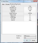
It is DDR2 Signal Integrity Model Editor in Altium. I have changed the Supply Voltage from 5V to 1.8V. All of them were 5V! I have check the IBIS model and there is nothing wrong with it.
SI2.jpg
In the resistance/capacitance tab, Voltage High and Pull-up Voltage are set to 5V and any attempt to change them was unsuccessful!
SI3.jpg
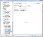
And at last the Signal Integrity analyse window that shows the 5V Top Value for all signals.
SI4.jpg
I have attached PCB directive with Supply Net value for every voltage Net in the schematic. And also they are appear in the PCB rules:
SI5.jpg

Please help me through it to change this 5V top value to 1.8V for DDR2 signals and 3.3V for others.
 

In that last picture, I see 11 supply net rules. As I doubt you would have 11 different voltage rails, you need to sort that out. For the time being you shouldnt have to worry about adding or deleting these from the PCB side. If the schematic is set up correctly then updating the PCB should give you the proper "Signal Integrity->Supply Net" rules. After a PCB update, you can then check the design rules from the PCB to see what is there and use that as a check to see that the schematic is set up right.

In an attempt to find where it's getting the 5 Volts from, are any of those supply nets in the the design rules from the PCB editor 5V, after performing an update?

It is DDR2 Signal Integrity Model Editor in Altium. I have changed the Supply Voltage from 5V to 1.8V. All of them were 5V! I have check the IBIS model and there is nothing wrong with it.
I remember seeng this as well, even when it was working. Please ignore this for the time being.
 

This is a board with FPGA and DSP and there is 4 voltage rails for FPGA and 5 for DSP and 1 for 0.9V DDR VTT and one aux 5V.
If all of them are not necessary I should delete them?

If the schematic is set up correctly then updating the PCB should give you the proper "Signal Integrity->Supply Net" rules. After a PCB update, you can then check the design rules from the PCB to see what is there and use that as a check to see that the schematic is set up right.

The updates are just fine, everything is updated correctly, I'll delete extra supply net rules and perform SI again.
 

I have deleted the extra Supply nets rules and just keep 1.8V and GND. But the result did not change.
 

Please check the following. Go through each and every schematic sheet, right click on it. Select "Options->Document Parameters" and see if there are any rules regarding voltage. These are somtimes left over after doing signal integrity analysis in schematic only mode. If there are, delete them and see how that goes
 

Thank you abaz, I've checked and there was nothing!!! I am really confused. I'll make a new project with just memory and the controller and try it again. Maybe I'll change the Altium version.
Have you ever tried other softwares for SI? I looked in CST but it is very complicated!
 

Thank you abaz.
I start to work with CST, it is capable of 3D analysis and I think it worth some try. I get some answers but still needs some work on CST.
Also I start to work with Mentor PADS v9.4 and it can import Altium pcbdoc files so no more need for script. Thank you very much.
If I face problem with Hyperlynx, I'll ask you.
 

I have simulated the clock net for a mobile DDR in both CST and Hyperlynx and got 2 different results! Here are the wave forms of both:
SI_Hyp_LPDDR.jpg
SI_CST_LPDDR.jpg
From the Hyperlynx results there are bad ringings but in the CST waveform of the same net, everything is just fine! There is just a 10 ohm series termination in the path.
I also could not find anything related to SPLIT PLANES in the Hyperlynx! This is from Hyperlynx hepl about planes: " This information is used by power-integrity simulation and not used by signal-integrity simulation."
So which one should we took into account? A sophisticated microwave simulator?/// I would be very happy if I could run the Signal Integrity simulation in the ALTIUM with Top Value Signals corrected to 1.8v!!!!!!!! There were not anything related to Stimulus voltage in the Hyperlyx nor CST, they find what they want just from IBIS file, but there is also a little work on nets in CST.
I'll try to run a 3D simulation in the CST and will compare the results. If you have any suggestions please tell me.
Also I could not find anything related to differential net simulation, is there anything related to this? In the CST it is a way to define signal driver in the differential form and the receiver is in diff form by selection the appropriate net model from IBIS file.
 
Last edited:

Probably a bit late but maybe worth a try. Seeing that you have tried some real Signal integrity programs, going back to Altium's might be a bit of a disappointment. Anyhow...

Found this amongst the scripts, one of which I pointed to earlier. In the readme.txt file it goes on to describe how when assigning an IBIS model to a part in altium where the pin can have various models (for example FPGA's) altium simply selects the first model in the list. This caused the high value of the pin to always be 5V. Not quite sure how or why but he went on to create a plugin (script) that allowed you to select the proper IBIS models for your parts.

Here's the link
https://code.google.com/p/altium-de.../detail?name=IBIS_Editor.zip&can=2&q=label:SI
 

Status
Not open for further replies.

Part and Inventory Search

Welcome to EDABoard.com

Sponsor

Back
Top