Vermes
Advanced Member level 4

- Joined
- Aug 2, 2011
- Messages
- 1,163
- Helped
- 0
- Reputation
- 0
- Reaction score
- 0
- Trophy points
- 1,316
- Activity points
- 22,318

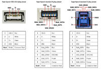
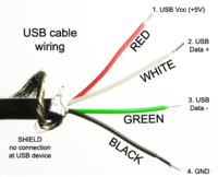
Let's start with defining pins of USB2.0 and USB3.0

- The GND line provides a common ground reference between the upstream and downstream ports. The maximum cable length is limited by the voltage drop across the GND load.
- The VCC lead provides power to the connected device (nominal 5V, but it usually differs from 5% 4.75 to 5.25V)
- D- and D+ are the data lines please read below
More specification
- the maximum voltage drop (for detachable cables) between A-series and B-series plus on Vbus is 171mV
- the maximum current for USB2.0 is 500mA and for USB3.0 is 900mA
- the maximum voltage drop for all cables between upstream and downstream on GND is 171mV
- the maximum voltage drop for all mated connectors is 27mV
- all hubs and peripheral devices shall be able to provide configuration information with as little as 4.00V at the device end of their B-series receptacle. Both low and high-power devices need to be operational with the minimum voltage.
USB uses a differential transmission pair of data and uses NRZI encoding (non return to zero inverted). Take a look on the picture below:

The level characteristics of USB voltage:
- static output swing of the driver in its low state must be below Vol (max) of 0.3V with a 1.5kOhm load to 3.6V
- for the high state Voh (min) must be above 2.8V with 15kOhm load to GND

The receiver defines a differential '1' as D+ 200mV grater than D- and a differential '0' as D+ 200mV less than D-. The polarity of the signal is inverted, depending on the speed of the bus. Therefore, the 'J' and 'K' states are used in signifying the logic levels. In low speed, a 'J' state is a differential 0. In high speed, 'J' state is a differential '1'.
After this short theoretical introduction, please take a look at the examples of practical use:
Car USB charger
This trivial device is very easy to make by yourself, but let's start with making a test cable for further use. You can create a new cable or use an old USB cable. Just cut one end of it.

After that, cut the WHITE and GREEN cable. You will need only the RED +5V and the BLACK GND one. This cable will be useful for testing USB ports. Why do you need it? The answer is obvious – the multimeter pins are hard to place in a USB port. If you used an old USB cable, you can use the other side to get a DATA+ DATA- test cable. If you need a professional cable, just get for example Degson connector and screw all cables to it.
To create a Car USB charger you will need 3 capacitors (two 10uF and one 0.1uF), and a voltage stabilizer. To get the USB voltage (5V) from car 12V output, you will need a L7805CV. Below, you can see the schematic:

Using the created earlier cable, do not forget to test the output voltage to prevent your device from damaging!
One last, very important thing – the temperature!
Power = (Vin – Vout) * Iout
We have Vin = 12V and Vout = 5V
Power = 7V * Iout
A standard USB has 0.5A, therefore, we will count it for this value.
Power =7V * 0.5A
Power = 3.5W
You will need a heat sink for 3.5W for example this one: https://www.tme.eu/pl/details/d01a/radiatory/stonecold/#
Summary:
-Supplied voltage by a host or a powered hub ports is between 4.75 V and 5.25 V.
-Maximum voltage drop for bus-powered hubs is 0.35 V from it's host or hub to the hubs output port.
-All hubs and functions must be able to send configuration data at 4.4 V, but only low-power functions need to be working at this voltage.
-Normal operational voltage for functions is minimum 4.75 V.
