Continue to Site

Welcome to EDAboard.com

Welcome to our site! EDAboard.com is an international Electronics Discussion Forum focused on EDA software, circuits, schematics, books, theory, papers, asic, pld, 8051, DSP, Network, RF, Analog Design, PCB, Service Manuals... and a whole lot more! To participate you need to register. Registration is free. Click here to register now.

Short Circuit Response of Buck Converter (Peak Current Mode Control)

Status
Not open for further replies.

celebrevida

Member level 2
Joined
Oct 25, 2016
Messages
47
Helped
0
Reputation
0
Reaction score
2
Trophy points
8
Activity points
524
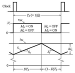
Schematic of a Buck Converter with Peak Current Mode Control
1600346215528.png

Let's say we have Vi=12V, Vo=5V, Rload=5 (So Iload=1A) at steady state.
Now I bring down Rload->0 (short circuit between Vout and gnd).

Bringing down Vo to zero should increase Vea to a high max value. (EA amp has high gain).
If Vsense=Ri*IL is unchanged, then the two curves should intersect at a later time and CMP resets the FF at a later time.
(Vsense is a ramp and with Vea being higher, it takes longer for the Vsense to reach Vea than before)
This means a larger Duty Cycle D.

But iL actually changed (at least its slope). It used to be (12-5)/L=7/L. But now it is 12/L so IL vs t is steeper.
If Vea never changed, then Vsense intersects Vea at an earlier time and reduces D.

I guess it isn't clear to me whether D ultimately decreased or increased.
Is it knowable or it just depends on particular values?

Okay, at this point, this Dnew (whatever it is) is locked right?

I mean Vea and IL slope are both maxed out and both can't change anymore with Vo shorted to gnd right?

So does this mean that IL(max) is now also maxed out and therefore this circuit is preventing the IL from running away?

Or am I missing something and IL will keep increasing cycle by cycle and blow up anyway somehow?

Thanks for any insight!
 

Attachments

  • 1600346353272.png
    1600346353272.png
    40.7 KB · Views: 157

The circuit is designed such that the current limit signal can override the EA signal and shorten the duty-cycle to limit the current, independent of the EA signal.
 

Hi,
R_sense is not uset to limit the output (load) current.

It is a part of the cycle-by-cycle regulation loop:
According output_voltage_error it charges the coil for a dedicated current to push a dedicated amount of energy to the ouput capacitor.

Klaus
 

The circuit is designed such that the current limit signal can override the EA signal and shorten the duty-cycle to limit the current, independent of the EA signal.
If you have only a iL perturbation, I definitely can see that duty cycle would be shortened. You'd shift Ri*iL upwards which intersects Vea earlier in tripping CMP comparator.

But it seems that if tie Vout to gnd, you'd have iL and Vea perturbation. In that case, it's not clear what the duty cycle becomes. Any insight there? Does it even matter?

Also would this circuit protect against shorting out Vout and limiting the iL and therefore output current as I believe it should?
 

In case of shorted Vo, IL will increase continuously for any D > 0. IL is however clamped by Ea finite output voltage range.
 

Hi,
R_sense is not uset to limit the output (load) current.

It is a part of the cycle-by-cycle regulation loop:
According output_voltage_error it charges the coil for a dedicated current to push a dedicated amount of energy to the ouput capacitor.

Klaus
So you are saying that it only limits iL from rising further per cycle but isn't meant to limit the load current in the long run?
In case of shorted Vo, IL will increase continuously for any D > 0. IL is however clamped by Ea finite output voltage range.

I'm confused. The max Vea would be Vdd. So each cycle, as soon as IL reaches Vdd/Ri, CMP trips and the Mp switch is OFF.

Do you mean that IL keeps increasing each cycle but then stops when you get to Vdd/(ai*R sense)? If so then it matches my understanding.

Or do you mean that this circuit only limits the amount of IL rise per cycle to Vdd/To but IL overall can keep rising forever? If so, how???
 

Okay, I've looked at this a little deeper and I think I understand now.

If you short Vout to gnd, you still limit the current rise per cycle to Vea_max/Ri (where Vea_max=Vdd of the EA amplier). During the ON cycle, the IL rises at the rate of (Vi-Vo)/L=Vi/L.

However, during the OFF cycle, you have dIL_off/dt = (0-Vo)/L=(0-0)/L=0. This means that IL never goes down and will keep rising cycle after cycle indefinitely. It doesn't matter what the duty cycle is.

So the peak current mode only limits the IL rise each cycle but doesn't limit the IL to rise indefinitely in the long run.

I have read that peak current mode control does provide simpler loop dynamics and less complicated feedback compensation. But other than this, I'm not sure what other advantage is there. Because peak current mode control doesn't actually limit IL or Iload like I originally thought so the name seems deceptive.
 

In our POL DC-DC design there were two comparators
per powertrain high side switch segment. One for the
demand signal (from error amp) and one for the
baclstop current limit (which we gave a set-resistor
pin for, to get a current; both comparators were
current-mode).

In this case your min PW is the comparator delay
(from sense-segment current over threshold, to
final FET gate). We found it to have pretty good
fidelity provided that the short is outboard of the
output filter inductor (as it would be for any
sealed "brick", but can't be counted on for a
board level construction that is exposed to the
outside world).
 

the top circuit / block diagram is not very well drawn. A practical circuit would show a limit on the Vea level - such that this then forms a hard current limit for the power system ....
 

the top circuit / block diagram is not very well drawn. A practical circuit would show a limit on the Vea level - such that this then forms a hard current limit for the power system ....

How so? Limiting Vea would impose a lower limit on how high IL can rise during the ON part of the cycle. But during the OFF cycle, you'd have VL=0 (or close to it) and so IL doesn't really drop much because dI/dl=0/L during OFF. IL would still grow each cycle and keep growing and growing.
 
Last edited:

but isn't meant to limit the load current in the long run?
Yes

Added: for sure it will limit the output current somehow. (The average output current can't be higher than the coil current).
But output current will still depend on output voltage in overload condition (when output voltage is below the setpoint)
But it dos not necessarily in the meaning of load protection or circuit protection. But it could be.

Klaus
 
Last edited:

So the peak current mode only limits the IL rise each cycle but doesn't limit the IL to rise indefinitely in the long run.
My expectation is that flip-flop R input has priority, thus if IL exceeds the limit calculated above, the output stage won't be turned on. In so far, the circuit limits IL absolutely.
 

Geez Wayne, placing a clamp on the level of Vea out will limit the current to a max value - irrespective of Vo, a shorted load - or anything else - please look harder at the ( note very good ) ckt posted ...
 

Okay I think I see what could be happening.

If IL > Vea/Ri, CMP asserts Reset and we go into OFF state. But I was wrong to say that because Vout is shorted to GND that therefore IL can't decrease. If there was current previous to switching to OFF, the inductor can bring the VL+ node to negative to allow continued current flow that is decreasing. At this point, we should drop below Vea/Ri and the CMP de-asserts RESET. So we cycle between Imax and some value below Imax. This all assumes that RESET has priority over SET. But if so, the peak current control should protect against short ckt in a Buck converter. Am I finally right?

And lastly, it seems that this peak mode control circuitry cannot protect against short circuit with a boost converter. You'd go into the OFF state which just means connecting an inductor between Vin and Vout=GND! So for boost converters, current mode control offers no short circuit protection, right?
 

Yes boost cant protect against shorted load........the short circuit current just flows from vin to vout, through the inductor and diode.

The attached LTspice sim shows what happens to the Buck when its output goes short.
LTspice is free download.
Just convert sim to .asc
Open it
Hit running man icon.

Note the short circuit current varies with variation of the current sense filter

The LT1243 has no LEB, so uses the currnt sense filter.

Normally your short circuit current depends on your LEB
(Leading edge blanking time)

Easy Peasy 's comment about the clamp on the vea output voltage was extremely relevant to this discussion.
Open the LT1243 datasheet and you'll see the clamp on the vea output.
Its usually clamped to 1v.
But some controllers clamp it to 100mV.
 

Attachments

  • buck 12v to 5v at 1A.txt
    5.8 KB · Views: 126
Last edited by a moderator:
Status
Not open for further replies.

Similar threads

Part and Inventory Search

Welcome to EDABoard.com

Sponsor

Back
Top