Welcome to our site! EDAboard.com is an international Electronics Discussion Forum focused on EDA software, circuits, schematics, books, theory, papers, asic, pld, 8051, DSP, Network, RF, Analog Design, PCB, Service Manuals... and a whole lot more! To participate you need to register. Registration is free. Click here to register now.
A rather vague question.. don't know what you are after.
Generally a transistor is a discrete semiconductor part.
A schmitt trigger is a circuit consisting of several electronic parts. To build a schmitt trigger you need transistors.
(I guess you already did an internet search ... )
So it's like comparing a brick with a house.
About current consumption. Depending on the circuit and the part values a transistor may consume from zero to extremely high current.
But usually a transistor is not used to consume current, but to control current.
I guess you have an idea in mind or have read some documents ... please give links to them and ask a more detailed question.
USB data bus is LVDS (TIA-644) physical / electrical
layer. It has little to do with either a Schmitt buffer
or a transistor although you -could- feed one side
of a LVDS pair to some single ended buffer -if-
the common mode control and the differential
outputs will give you a suitable voltage center
and swing. Better however to just get a LVDS RX
chip with the desired logic output voltage levels.
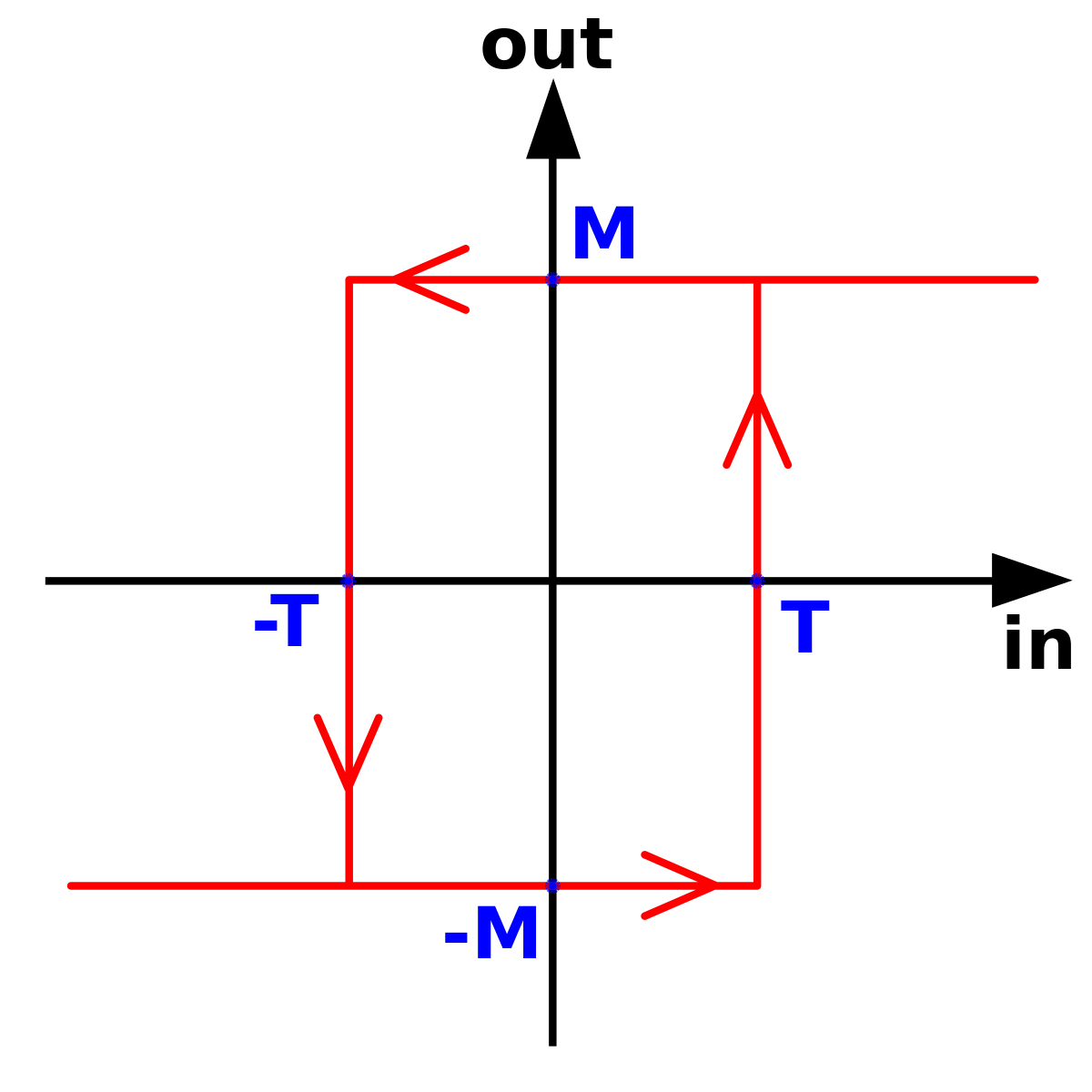
Schmitt buffers are used to deal with noise riding
on the signal, or signal risetimes so slow that
noise would induce chatter in a simple inverter.
If the hysteresis band exceeds noise amplitude
then you can get a single clean transition out of
a somewhat messy signal. To a point.
This site uses cookies to help personalise content, tailor your experience and to keep you logged in if you register.
By continuing to use this site, you are consenting to our use of cookies.