Continue to Site

Welcome to EDAboard.com

Welcome to our site! EDAboard.com is an international Electronics Discussion Forum focused on EDA software, circuits, schematics, books, theory, papers, asic, pld, 8051, DSP, Network, RF, Analog Design, PCB, Service Manuals... and a whole lot more! To participate you need to register. Registration is free. Click here to register now.

SG3525 power converter DC24V to DC320V 30A

Status
Not open for further replies.

ilacmano

Newbie level 6
Newbie level 6
Joined
Aug 30, 2010
Messages
11
Helped
0
Reputation
0
Reaction score
0
Trophy points
1,281
Location
Croatia
Visit site
Activity points
1,392
Need help for my projects SG3525 Power converter input DC24V output DC320V 30A.
If enough 12 x IRFPS3810 for this output and if this project may be realistic work.

Need help for transformer primary/secondary number of wire and wire SWG. Which transformer cores may be use.
Which maximum fuse must be used for AC240V output.

This power converter driving True Sine Wave Inverter with ATMEGA16/32, 2 x IR2110 and 4 x IRG4PC50FD outputs AC 240V 25/30A 50Hz.
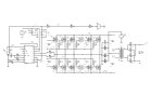
smps converter sg3525 dc24v output dc320v 30a.JPG
 

I can't help with the transformer wiring but please realize this circuit will consume more than 400 Amps so even the wiring outside the transformer will have to be very thick.

Brian.
 

For such a high power level, a push pull converter is not suitable. You should use a phase shift controlled full bridge, with FETs rated for 40V, not 100V. If possible you should use MOSFET modules instead of leaded or SMT devices, so that you don't have to parallel many FETs (it's difficult to parallel so many devices effectively).

The transformer primary won't have a gauge. You will need to use flat windings, with an appropriate cross sectional area. The secondary may also need to be flat wound.
 

320 V @30 A = 9600 ~10 KW, without a fuse/safety cut out in sight!. Any fault is likely to produce an explosion and a total rebuild. There is also the output transformer, huge lump of ferrite and a severe mechanical problem in winding it, or even finding "wire" of the right cross sectional area. I think it would have to be forced air cooled or even water cooled. I think a more sane way would be to use 5 inverters connected in parallel, but actually build 6, so you have a spare that can be used to restore service in the event of a single failure. These inverters would still be rated at 2 KW each, so still ambitiously large. But at least with a modest (?) 100A input to each, a conventional contacter can be used to switch them off due to a current overload or other reason (most likely over temperature due to obstructed cooling filters?).
Frank
 

This is a very ambitious project, the input current will be 400 amps at full power, it is usual to divide and conquer for such projects, i.e. develop a 50amp input stage, and use 8 of these to get your 320VDC @ 30A, if this is a commercial project, we could help you get to where you want to be...
 

Hi,
It is better to make 4 Nos of 80v 30A power supply and add the output so that You get the Required Power
Design will be simple and easy to wire
 

I think this is not true sine wive inverter, this is modified sine in best way with filtering on output, and on higher current load there will be deformation of sine. I think this is not good inverter design, specially for this power. Input voltage is not appropriate for that power. Also I supose this inverter have high standby current consuption from batteries.

Maybe you own personal factory of lead acid batteries, and you can change everyday new batteries/bank of battery. ;-)
 

Hi tpetar,
The above cct is only the DC-DC converter part of the mentioned inverter
 

Status
Not open for further replies.

Similar threads

Part and Inventory Search

Welcome to EDABoard.com

Sponsor

Back
Top