Continue to Site

Welcome to EDAboard.com

Welcome to our site! EDAboard.com is an international Electronics Discussion Forum focused on EDA software, circuits, schematics, books, theory, papers, asic, pld, 8051, DSP, Network, RF, Analog Design, PCB, Service Manuals... and a whole lot more! To participate you need to register. Registration is free. Click here to register now.

SG3525 Inverter circuit problem.

Status
Not open for further replies.

Rickooo

Member level 3
Joined
Aug 28, 2018
Messages
67
Helped
0
Reputation
0
Reaction score
0
Trophy points
6
Activity points
507
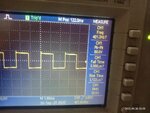
Hi, I am designing 12V DC to 220V AC 400Hz inverter circuit. With a reference of https://www.instructables.com/200Watts-12V-to-220V-DC-DC-Converter/ article, I tried not so similar circuit. I used 150nF and 13k to generate 400Hz. And when tested with CRO, I got constant 400Hz on Pin 14 and 11. Please look to the image number "img1".

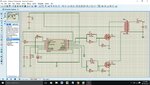
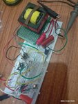
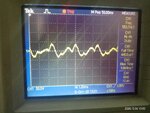
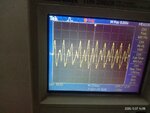
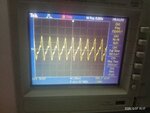
Look image "img2" for whole circuit. Look image "img3" for tested circuit. Look image "img4" for output wave.

Now, when I added the transformer, 2 things happen:
1. Frequency fluctuate. 500 Hz - 1.2k Hz
2. Wave is not sinusoidal.

Please guide me and suggest me, what should I do now?

Thanks in advance.
 

Attachments

  • img1.jpeg
    img1.jpeg
    84.8 KB · Views: 176
  • img2.jpeg
    img2.jpeg
    251.9 KB · Views: 174
  • img3.jpeg
    img3.jpeg
    99 KB · Views: 137
  • img4.jpeg
    img4.jpeg
    83.9 KB · Views: 142

Hi,

what kind of 12 V power supply do you use, by means of maximum output current?
How does the waveform looks like on the secondary side of your transformer when L1 and C3 are not populated?

BR
 
You probably need some decoupling on the supply for the SG3525.
Such a breaboard is also no good for switching power circuits.
 

Depending on power you are trying to get -
  • you need serious decoupling of the input supply, i.e. input caps and a stiff power supply.
  • the transformer must be designed for 400Hz.
  • the filter must be designed with regard to max current in L & C - at no load it will be undamped and will likely ring a lot.
  • if the filter is wrong there will be large currents in the mosfets and bang.
  • how have you ensured the symmetry of flux in the transfomer?
 

Hi,

what kind of 12 V power supply do you use, by means of maximum output current?
How does the waveform looks like on the secondary side of your transformer when L1 and C3 are not populated?

BR
The power supply is DC power which used in lab. 30V 5A. I am giving 12V.
When I test with no capacitor, transformer make noise and cant detect the wave as their is much noise. But, when I added 3300uF 25V capacitor at the input side of supply, I got the wave as shown in image added below, by adding 3.3uF 400V non polarized capacitor (no inductor). But, its not purely sine and frequency also fluctuate from 379 Hz - 739 Hz.

Which component should I add now and why to solve 2 problem: 1. Sinusoidal wave. 2. Frequency is not stable?

Loking for the guidance. Thanks
 

Attachments

  • img5.jpeg
    img5.jpeg
    77.2 KB · Views: 194

Hi,

how much current do you source from your 12 V power supply? As a multimeter and the built in amp-meter of a benchtop power supply only shows the RMS value, the transient drain-source current of your switching MOSTs are of interest. Therfore use a small valued resistor (< 1 \[\Omega\]) in series from source to ground and have a look with your scope.

The attached capacitor on the secondary side represents a low impedance at 400 Hz, this impedance is transformed to the primary side and where it represents an even smaller impedance.

the transformer must be designed for 400Hz.

Which transformer do you use?

BR
 

Which transformer do you use?

BR

It's a ferrite core transformer. Please look the image.
Image with "img5" is with capacitor 3.3uF 400V.
Imgae with "img6" is with LC filter, with Inductor 1uH 3A and capacitor 3.3uF 400V.

Please find the difference in wave shape. Please suggest me the solution to make it purely sine.
 

Attachments

  • img6.jpeg
    img6.jpeg
    89.9 KB · Views: 174
  • img5.jpeg
    img5.jpeg
    77.2 KB · Views: 165

1. I don't understand how you expect sinusoidal 400 Hz output from your inverter. The output switches are driving a square wave, the output filter has about 15 kHz cut-off frequency.

2. There's no frequency fluctuation in the post #5 and #7 waveform, only an erroneous oscilloscope frequency measurement.
 

To filter a square wave output of the Tx into a sine wave - ideally you need a 2 stage filter - the Fo of these filters will generally be below 400Hz - the first stage by quite a bit i.e. 1 / (2. pi . sqrt (LC)) << 400Hz

the L in the 1st stage needs to be sized to limit the ripple current in the filter for the 220V pulses that are hitting it e.g. 200V for 1.25mS across 1mH = 250A

( V/L = di/dt ) so 1mH is too small ...!

To get down to +/- 1A delta I, we need L = 0.25 Henries, ( 250mH ) - i.e. quite large, and 1A on the HV side is 1 x 200/12 = 16.67A on the LV side

So your fets will need some pretty good heatsinking just to run at no load ...!

Say we make the filter Fo ( 1st stage ) = 33Hz ( well below 400Hz ) we need Co = 93uF at 275Vac rated ( and at least 1A rated )

So you need big L's & C's at 400Hz even to filter low power ( say 200 Watt ) even in the 1st stage of a filter

also if your power source cannot supply 12V @ 20A you will have real trouble with circuit stability ....

if your ferrite transformer is not rated for 200V 400Hz on the HV side and 12V 20A on the LV side - you will have more issues

dB/dt = V / ( N. Ae ), So allowing Bmax = 0.3T, dB = 2x = 600mT = dt. 12V / ( N. Ae ) [ Ae = core effective area in m^2]

if Ae = 1.5 cm diameter for example ( 176mm^2) , then N can be as low as 142 turns ( HV = 2400 turns )

I don't think your Tx is made this way ...(?) to get to 10 turns on the 12V side ( at 400Hz ) you need a core area of 2500 mm^2 ( and 180 turns on the 220V side )

or 50 x 50 mm ( think E65 core - but 5 of them side by side ), at the moment the transformer is shorting out the LV side as the core goes to saturation at fairly low currents ( i.e. the Bmax tries to go way above 300mT but plateaus and the pri current spikes way up high ... )

happy designing
 
Last edited:

Status
Not open for further replies.

Similar threads

Part and Inventory Search

Welcome to EDABoard.com

Sponsor

Back
Top