Continue to Site

Welcome to EDAboard.com

Welcome to our site! EDAboard.com is an international Electronics Discussion Forum focused on EDA software, circuits, schematics, books, theory, papers, asic, pld, 8051, DSP, Network, RF, Analog Design, PCB, Service Manuals... and a whole lot more! To participate you need to register. Registration is free. Click here to register now.

[SOLVED] SG3524 100v 25a smps

Status
Not open for further replies.

SSShocked

Member level 5
Joined
Apr 24, 2012
Messages
86
Helped
1
Reputation
2
Reaction score
1
Trophy points
1,288
Location
Bulgaria :(
Activity points
1,859
Hi all
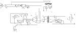
i have found this schematic in this forum
(the second one, the bad quality)
it was said that this is a low noise, high eff. adjustable lab smps with adj. current limiting
so i decided to redraw it and mod it
i am quite lazy so i just copied the the values
the transformer primary will be 22 turns CT on etd49 core it will work at 200khz
i was too lazy to add the output filter
(the first, high quality)
the IGBT is IRGPS40B120UP
https://www.google.bg/url?sa=t&rct=j&...6Z6Npw5gD0-LoA

so, is it going to work
if not tell me how to do it
 

Attachments

  • 100v_25a.gif
    244.8 KB · Views: 200
  • 3524.jpg
    3524.jpg
    435.4 KB · Views: 393
Last edited:

yes i think i should work theoriticaly but you can give it a trial it might work practicaly.
 
i heard the igbts must be driven trough opoisolators
what about the 22t on etd49
for 400vdc (will use PFC )
 

yes opto- isolator is good for igbt but you can also used IR2112. and many h bridge drivers
 
so i will remove the PP bridge and will put the ir2112
what about the 22t on etd49
and the most important is it going to be
adjustable 2.5-100v 0.1-25a
 
Last edited:

Doomed to failure?

The discussion sounds confuse. You are talking about a transformer push-pull rather than a bridge circuit. Why should it use opto-isolators or bootstrap drivers? The IGBT schematic has several errors, it looks like a sloppy copy of the original schematic. A synchronous rectifier e.g. can't work with IGBTs, there should be NMOS transistors instead. Missing emitter pull-downs at 3524.

Building high power, high voltage circuits requires accurate designs and every detail well considered. Otherwise it's doomed to failure.
 
i heard it should have opto-isolators or bootstrap drivers
i saw it in many schematics, even comercial

yes it is a copy
i said it in the beginning

why the SR can't work with igbts

what do you mean by Missing emitter pull-downs at 3524.

please take a deep look at the schematic and tell me all the errors
 
Last edited:

Yes ayou talked about a copy, but you didn't tell clearly which schematic is the copy. If the IGBT schematic is a copy, I won't expect MOSFETs arbitrarily changed to IGBTs.

My generally suggestion is, if you don't understand every detail of the original circuit, don't change it. Or change it for trial, but don't expect it's working.

The pulldown point is just a matter of 3524 operation details. If you read the datasheet thoroughly, you'll understand it. The other, hand-sketched schematic has a pull-down, by the way.

The purpose of synchronous rectifier is to get a lower forward voltage than with regular diodes. If you look sharp, you realize that the original NMOS transistors are operated in reverse conduction. In case of doubt, you can refer to the IR11682 datasheet. IGBT have a rather high foward voltage (e.g. 1.5 to 2V), aren't reverse conducting and usually don't tolerate reverse voltage.
 
Hello ssshocked, what fvm is trying to tell you is if you look at your oscillator SG3524 pin 11 and 14 are used as output oscillator and their will be need of pulldown resistors to will down the base of your npn transistors ,and you can only use bootsrap when you are dealing with high side where not pushpull .
 
the one with the igbts and the PP transformer is the edited copy
so i will use mosfets for SR
the question is whed i add the pull downs i it going to work
i will use igbt gate drivers
is it giong to be adjustable 2.5-100v 0.1-25a
do you have ExpressPCB so i can send you the schematic

- - - Updated - - -

ok
if i add them and put mosfets on the SR i is going to work
 

The IGBT push-pull circuit can work and won't need other drivers than shown in the schematic. But the constant voltage and current controller requires a common ground of output circuit, controller and the mains power supply. Or additional optical isolation.

The transformer push-pull is at risk to exceed IGBT voltage ratings if it's not supplemented by a clamp or snubber circuit. You have written about 200 kHz which is somehow illusional with IGBT switches.
 
look at it's datasheet
it has nanosecond switching times
it is also designed for smps
what do you mean by common ground
connect the 3524 gnd to the igbt's
or input and output gnd
you mean to use opto. like every other smps
i didnt used opto. because the low accuracy
i will put a RC snubber
https://www.google.bg/url?sa=t&rct=j&...6Z6Npw5gD0-LoA
 
Last edited:

did you mean't these changes
Something of this kind.

The not-so-easy- point is optical isolation of analog measurements. In the original design, the measurement reference is inside 3524. It allows a rather exact voltage regulation. An opto coupler is neither linear nor has a well defined transfer characteristic. To achieve good voltage regulation quality, you'll ususally have a reference on the seondary side, e.g. using TL431 and transmit only the error signal across the potential barrier, not requiring absolute accuracy or linearity.
 
is the pull down like that
do you mean to connect tl431 between FB and GND
can you explain more briefly
 

is the pull down like that
Yes
do you mean to connect tl431 between FB and GND
What do you mean with FB?

I primarly wanted to emphasize the problem involved with opto-isolation of analog signals, not suggest a ready-made solution.
 
FB-feedback i think to remove the isolation, so i can have high accuracy
i have seen, that most of the laboratry smps don't use optoisolators
fixed 2.jpg
like that
 

Did you notice that the 3524 controller is directly connected to AC power supply? Having no isolation, either for output feedback or gate signals, means that the DC output will be directly tied to AC power supply, too. Rarely wanted for a lab supply.
 
no
it is powered trough a separate, isolated 16v4a dc line
same with the bd13x
the synchronous rectifier is powered from a separate secondary turn
again 16v4a
the igbts are powered trough the PFC
didn't you noticed the 2 secondary turns transformer
 

didn't you noticed the 2 secondary turns transformer
Did I notice it?

I'm talking about the power circuit, not the auxilary supply. It connects the primary controller directly with AC power input.
The power output is isolated by the high frequency transformer. But the voltage and current feedback requires a common ground. Or differential amplifiers with huge common mode range, effectively impossible for a feedback controller.
 
Status
Not open for further replies.

Similar threads

Part and Inventory Search

Welcome to EDABoard.com

Sponsor

Back
Top