Continue to Site

Welcome to EDAboard.com

Welcome to our site! EDAboard.com is an international Electronics Discussion Forum focused on EDA software, circuits, schematics, books, theory, papers, asic, pld, 8051, DSP, Network, RF, Analog Design, PCB, Service Manuals... and a whole lot more! To participate you need to register. Registration is free. Click here to register now.

seven segment display simulation problem, help

Status
Not open for further replies.

the_dynamo

Newbie level 4
Joined
Feb 6, 2015
Messages
7
Helped
0
Reputation
0
Reaction score
0
Trophy points
1
Activity points
59
Hi,
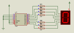
I am very new to proteus and would much appreciate a little help. I have made a schematic in which to count with 2 seven segment displays. I thinkit is all working as I can see the red/blue switching colours. But the displays remain dark. I think I have them powered but nothing. They are common cathode. Any advice would be gratefully welcomed, thanks.

Untitled.jpg
 

330k (330000 Ohm) is too high.
Replace the display segment resistors with 330 Ohm and remove the ground side resistors.
 
Yes, thank you. The 7seg displays are now working. But they are not counting numbers. They are displaying strange displays. I have run it step by step too and it is not working properly for some reason. I have noticed too that my link test button does not light all the LEDs as I planned for some reason. Could you help with that too? Thanks again for your time.
 

In my messages after simulation is stopped it has 4 errors.

Pin "CX" is not modelled U3:A
Pin "RX/CXCX" is not modelled U3:A
Pin "CX" is not modelled U3:B
Pin "RX/CXCX" is not modelled U3:B
 

The display should be common-anode type since you're using 74LS47.

Notice the bubbles at the outputs of the LS47?

Allen
 

Attachments

  • 7 segment LED.png
    7 segment LED.png
    14.1 KB · Views: 101
Last edited:
Thanks for all the advice, very helpful, and it is now working. I have one more small favour. I need help with the equation and/or my poor math. If for example I needed to make my counter count at one count per second, how would I achieve this? I believe it would be by adjusting the R1 and R4 resistor values. I have tried this but can not work out the relationship between them and the timing. I have hooked up an oscilloscope (image included) and I am not sure what I am looking at. Would I be correct in say that ChA (pin3 on U1) controls the period, and ChB (pin3 on U2) controls the frequency? If that is correct i'm still not sure how this effects the counting and how I would work out my resistor values to achieve a certain speed. Thanks in advance to anyone who can enlighten me of the math so I can adjust my timing circuit.

- - - Updated - - -

Untitled.pngUntitled1.png
 

Status
Not open for further replies.

Similar threads

Part and Inventory Search

Welcome to EDABoard.com

Sponsor

Back
Top