Continue to Site

Welcome to EDAboard.com

Welcome to our site! EDAboard.com is an international Electronics Discussion Forum focused on EDA software, circuits, schematics, books, theory, papers, asic, pld, 8051, DSP, Network, RF, Analog Design, PCB, Service Manuals... and a whole lot more! To participate you need to register. Registration is free. Click here to register now.

Setting Up Optimization in HFSS Circuit Designer

Status
Not open for further replies.

denizduran

Member level 2
Joined
Sep 14, 2021
Messages
48
Helped
0
Reputation
0
Reaction score
1
Trophy points
8
Activity points
463
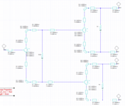
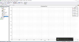
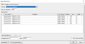
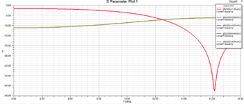
I am designing a 4 way wilkinson power divider to feed my antenna. The design frequency is 10GHz but without optimization or tuning, the S11, S21, S31, S41, S51 shift in frequency and I cannot get the desired results for 10GHz. That is why I set up an optimization to shift back the frequency to 10GHz, however, when the optimization goes through my S11 plot does not show up. It is almost like the linear network analysis is neglected. I have attached my zipped .aedt file . Please help me figure out how I can retrieve my S11 results properly.
 

Attachments

  • Feed_Network_Wilkinson.zip
    44.5 KB · Views: 87

ansys_error.PNG


Make your project as archive then post it.
 

This is not Ansys EDT archive. In order to make it archive in Ansys EDT , File-->Archive
EDT will create a special archive file with an extension *.aedtz, post it here.
Don't forget to add necessary file.
ansys_archive.PNG
 

    denizduran

    Points: 2
    Helpful Answer Positive Rating
Sir, when I try attaching the files the error given below shows up.


Screen Shot 2021-10-04 at 18.47.43.png


Instead, I will attach the circuit and my results. As a next step, only if it is suitable for you, we can exchange emails for me to send you the file.

To state the problem again, when I setup an optimization and go through with it in order to shift the frequency to my operating frequency (10GHz) I cannot get any result for my S parameters. I set up the optimization variable as length from -1mm to 10mm. Without the optimization I obtain the S-parameter plot as the last attached screenshot.
 

Attachments

  • Screen Shot 2021-10-04 at 18.50.11.png
    Screen Shot 2021-10-04 at 18.50.11.png
    80 KB · Views: 125
  • Screen Shot 2021-10-04 at 18.50.30.png
    Screen Shot 2021-10-04 at 18.50.30.png
    142.7 KB · Views: 122
  • Screen Shot 2021-10-04 at 18.50.56.png
    Screen Shot 2021-10-04 at 18.50.56.png
    43 KB · Views: 112
  • Screen Shot 2021-10-04 at 18.56.04.png
    Screen Shot 2021-10-04 at 18.56.04.png
    44.1 KB · Views: 125

Because no "Optimization Variable" to play around..
You have to assign appropriate variables for certain W ( Width) and P(Length)..
I will show you how to do..
 
Because no "Optimization Variable" to play around..
You have to assign appropriate variables for certain W ( Width) and P(Length)..
I will show you how to do..
I assigned a variable named "length" for HFSS to adjust the width or length of the transmission lines but I guess I did something incorrect. Your help will be much appreciated..
 

Delete your variables. they are useless..
Attribute 2 variables to each element symmetrically get a symmetric layout like this.
ansys_optimized_wilkinson.png

You will see these variables in Circuit-->Design Properties then
ansys_optimized_wilkinson_variables.png

I have optimized your circuit but you should also learn how to do it..
ansys_optimized_wilkinson_out1.png
ansys_optimized_wilkinson_out2.png
 
Last edited:
Thank you Sir I appreciate the help. I will apply the steps you have taken to my circuit and try to get the same results!
 

Status
Not open for further replies.

Part and Inventory Search

Welcome to EDABoard.com

Sponsor

Back
Top