Continue to Site

Welcome to EDAboard.com

Welcome to our site! EDAboard.com is an international Electronics Discussion Forum focused on EDA software, circuits, schematics, books, theory, papers, asic, pld, 8051, DSP, Network, RF, Analog Design, PCB, Service Manuals... and a whole lot more! To participate you need to register. Registration is free. Click here to register now.

Series vs shunt ohmmeter

Status
Not open for further replies.

tahir4awan

Full Member level 4
Joined
Nov 29, 2010
Messages
208
Helped
16
Reputation
32
Reaction score
17
Trophy points
1,308
Location
Germany
Activity points
3,084
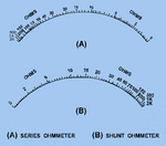
As we know the difference between series and shunt ohmmeter, but I have a confusion. I have searched, what is the use of series and shunt ohmmeter? Mostly analog multimeter we use today are series type ohmmeter. But why not shunt ohmmeter. I have searched thai question, and what I have found that shunt ohmmeter are used for low resistance from 5 to 400 ohms. Which is strange. I have seen meter with such scale. In a website, was written this and in the same website is a picture of series and shunt ohmmeter scales with same ranges but opposite deflection.


My question is, what is really the use of shunt ohmmeter? Are series and shunt measuring range same but with opposite deflection?


Thanks in advance.
 

Attachments

  • 32NE0243.gif
    32NE0243.gif
    4.7 KB · Views: 243
  • Screenshot_20201224-093709.png
    Screenshot_20201224-093709.png
    332.2 KB · Views: 243

My question is, what is really the use of shunt ohmmeter? Are series and shunt measuring range same but with opposite deflection?


When you want to measure voltage, you use a meter with a high series impedance. The meter is inserted in parallel with the voltage source and because of the high series resistance of the meter, the loading on the circuit under test is minimal. Or course the meter needs some current to work and the meter series resistance is the voltage sensitivity specification for the meter.

When you want to measure the current, the meter must use a low resistance shunt. The meter must be inserted in series with the current source and because of the low impedance the current is only minimally disturbed. The shunt is in parallel with the meter coil and the shunt value is selected depending on the sensitivity needed for the current range.

By the way, what you call an ohmmeter, is basically is current meter (for classical moving coil galvanometers) or is a voltmeter (most electronic meters are measuring the voltage) but they can be adapted for measuring voltage, current or resistance.
 

I didn't get it. I have attached pictures stating series and shunt ohmmeter scales. For series ohmmeter the needle deflects from infinite to 0, while for shunt it deflects from 0 to infinite.

Also in the second picture it is clearly stated, shunt ohmmeter are used to measure low resistance from 5 to 400 ohms.

I have forgotten, but I think I have seen this shunt ohmmeter with opposite deflection. But I am not sure.

It is clearly stated in the attached picture, that shunt ohmmeter are not used because they can measure only low resistance.

Can you please see the attached pictures, and explain. The scales ar e for Resistance not for current.


Thanks
 

Are you still using analog ohmmeters? If I remember right, I stopped it 30 years ago.

Digital ohmmeters are almost exclusively using a shunt circuit, constant current source and measuring the voltage drop across the resistor under test. This way you get a simple linear correspondence between resistance and measurement. The analog shunt circuit exposes a nonlinear relation because it uses a voltage source with series resistor rather than a current source for excitation and a relative low resistance meter to measure the voltage drop.
 

No I am not using it. I am doing 3 years diploma in electronics in germany. My teacher told me to make notes on series and shunt ohmmeter. So I came across this problem. I am cleared with series ohmmeter but not sure about shunt ohmmeter.

My question was if shunt ohmmeter exists then why it is said it is used for low resistance, while we normally use analog ohmmeter from 0 to 2k resistance.

Please note that I am not taking about current meter or voltage meter. My question is only about shunt ohmmeter. That's why is have attached the picture.

Thanks
 

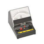
This is the shunt ohmmeter. As you can see the scale range is very low.
 

Attachments

  • untitled-500x500.png
    untitled-500x500.png
    143.6 KB · Views: 171

The range is set by the circuit impedance, meter impedance in parallel to the ranging resistor. The circuit impedance of the meter in post #6 is about 10 ohms.

Have you compared the circuits of shunt and series ohmmeter?
 

The shunt ohmmeter is cousin to the tactic of measuring output impedance of an IC, by attaching a load, causing voltage to drop, and when voltage drops to half it tells you that load and output impedance are equal.

The method could be called wasteful since the battery is continually drained although it's only an amount sufficient to cause full-scale meter reading. That is the idle (default) position of the needle. Notice that shorting the leads causes the reading to drop to zero.
 

Once you understand how the measurements of current and voltage are done, the rest is simple.

Resistance is always measured indirectly, either as a current or a voltage. It is an active measurement.

If you want to measure an unknown resistance, you have two options.

1. Apply a const voltage and measure the current current flow. As the V is constant, R will be inversely proportional to the current. So this will give you a non-linear scale, zero current corresponding to an infinite resistance. Good for measuring high resistances.

2. You can also apply a const current through a resistor and measure the voltage across it. Now the voltage drop will be linear and proportional to the resistance. Zero voltage drop now corresponds to a zero resistance. Good for measuring low resistances.

(in real life, the scales are not linear - or reciprocal - because all voltage measurements take some current and all current measurements cause some voltage drop. In other words, all meters have some finite resistance).

I hope you should be able to understand the basics now.
 

As others have mentioned, it is basic electrical theory.
in this case: that the algebraic sum of the currents entering a node is always zero.
 

Once you understand how the measurements of current and voltage are done, the rest is simple.

Resistance is always measured indirectly, either as a current or a voltage. It is an active measurement.

If you want to measure an unknown resistance, you have two options.

1. Apply a const voltage and measure the current current flow. As the V is constant, R will be inversely proportional to the current. So this will give you a non-linear scale, zero current corresponding to an infinite resistance. Good for measuring high resistances.

2. You can also apply a const current through a resistor and measure the voltage across it. Now the voltage drop will be linear and proportional to the resistance. Zero voltage drop now corresponds to a zero resistance. Good for measuring low resistances.

(in real life, the scales are not linear - or reciprocal - because all voltage measurements take some current and all current measurements cause some voltage drop. In other words, all meters have some finite resistance).

I hope you should be able to understand the basics now.

I have here some confusion. You said for the measurement of high resistance you have used constant voltage.
And for the measurement of low resistance you have used constant current.

We use series ohmmeter for high resistance and shunt ohmmeter for low resistance.

Do you mean that, in series ohmmeter the voltage is constant and in shunt ohmmeter the current is constant?
 

A real meter (the needle type; they have a coil suspended between the pole pieces of a permanent magnet; the digital meters are a different beast all together) has some finite resistance and needs some finite current to produce a deflection. The deflection is directly proportional to the current through the coil (the needle is attached to the coil via a spring; also called moving coil meter) but some voltage is needed because the coil has some resistance. If you apply double the voltage, the current through the coil doubles and the deflection is now twice the earlier value. So the same meter can measure both voltage and current.

But real life is not so simple: we want to measure voltage when the source may have considerable impedance. If the meter draws any current, the voltage being measure will undergo some change. So for voltage measurements we want the meter to have very high resistance. In other words, the meter should draw very little current.

Consider you have a const voltage of 1V (just to fix ideas). When applied directly, you produces a deflection of the meter of 100 units. The resistance of the meter is R (say). Now you put another resistance of R in series. The current will now become half (circuit resistance has become 2R)- 50 units. So when the resistance is zero, the reading is 100, when the resistance is R the reading is 50 and when the resistance is 9R, the reading will be 5 units. When the resistance is infinity, the reading will be zero. This mode is suitable for measuring resistance values say upto 100R. If the meter resistance is 1K, then the practical range will be 10 to 100k for resistance measurements.

You can also put the unknown resistance in parallel to the meter. When the unknown resistance is R, the current through the coil is reduced by 1/2 and so is the deflection. So the 50% deflection point will be same. When the parallel resistance is 9R, the current through the meter is now 10 times larger and deflection will be 90 units. When the resistance is infinity, the meter will show a reading of 100.

For measuring very high resistances, we use a very high applied voltage (say 100-500V) and measure the very small current using a sensitive meter. For measuing very low resistances, we pass a very high current and measure the voltage drop using a sensitive voltmeter (four point probes are needed).
 

All ohm-meters are shunt types as the Rx to be measured goes in parallel with the measuring device - the current flows in a series loop during the test - your question is non sequitur - you need to do more reading
 

I've been using an analog Chinaglia Cortina multimeter til the eighties. In the ohms range, the DUT is series connected with batteries (3V respectively 25.5V for the highest range). The meter is measuring the current through the DUT, in so far I would call it a series circuit.

1609326620505.png

1609327175355.png
 

For measuring very high resistances, we use a very high applied voltage (say 100-500V) and measure the very small current using a sensitive meter. For measuing very low resistances, we pass a very high current and measure the voltage drop using a sensitive voltmeter (four point probes are needed).

Conventional meters (the good old D'Arsonval movement based) are useless to measure small or high resistances. We use high voltages (500V-1.5kV) to measure insulation resistances (Meggers or MegOhm Insulation testers) that can be typically 100M to 10G Ohms. To measure resistances of transformer secondaries or motor windings, that can be typically 1 to 1E-3 Ohms, we need a 4 point Kelvin measurement setup. Practical meters have different ranges (switchable) so that the unknown resistance can be measured relatively accurately. For accurate reading, you should set up a Wheatstone bridge measurement. It is very difficult to measure very low resistances or very high resistances accurately.
 

Status
Not open for further replies.

Similar threads

Part and Inventory Search

Welcome to EDABoard.com

Sponsor

Back
Top