Continue to Site

Welcome to EDAboard.com

Welcome to our site! EDAboard.com is an international Electronics Discussion Forum focused on EDA software, circuits, schematics, books, theory, papers, asic, pld, 8051, DSP, Network, RF, Analog Design, PCB, Service Manuals... and a whole lot more! To participate you need to register. Registration is free. Click here to register now.

[SOLVED] Series Pass Transistor

Status
Not open for further replies.
P

ParkerMike

Guest
What do Series Pass Transistor do? or used for?

I seen them used as a switch

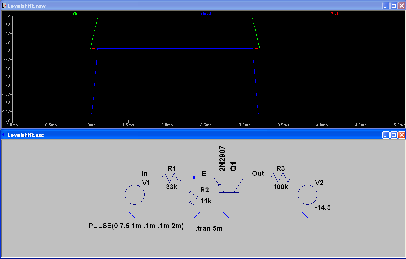
In the schematic it's a series pass transistor

I'm not sure why the designer used the transistor in this configuration because the base is grounded with the emitter at Negative - 14.5 volts

The Only thing I can think of is because a Negative -14.5 vdc would damage the base to emitter junction if they used it in a different transistor switch configuration


transistor switch#1.jpg
 

Those are PNP transistors and it's the collector pulled to -14.5V, not the emitter.
Without the rest of the schematic it's difficult to put the configurtion into perspective but it is certainly an acceptable way to use the transistor. It doesn't matter what voltage is on the base, it's the difference between base and emitter that makes it conduct or not.

Brian.
 

Most likely the transistors in common base circuit are working as level convertors from positive to negative logic.
 

Most likely the transistors in common base circuit are working as level convertors from positive to negative logic.

How can a transistor in series convert a positive logic to a negative logic?

How can a transistor in series be a level convertor?

What have you seen in circuit or designs that use transistors in series? besides in series regulators

What are series transistors used for?
 

Most likely the transistors in common base circuit are working as level convertors from positive to negative logic.
but the transistor in common base configuration isn't an inverter!

- - - Updated - - -

How can a transistor in series convert a positive logic to a negative logic?

How can a transistor in series be a level convertor?

What have you seen in circuit or designs that use transistors in series? besides in series regulators

What are series transistors used for?

I don't have your schematic completely . but if your mean of series transistor is transisitor in common base configuration they don't play as an inverter. sometimes we use them in amplifiers as a cascode device to increasing the output resistance and also for widening the bw of amp because they have good freq response because they don't have miller cap and also they used for isolation between in and out and etc . if your question is another thing else let me know!
 

but the transistor in common base configuration isn't an inverter!
I was talking about a level converter, not an inverter. E.g. +15V to -15V logic.
 

Most transistors I see on schematics the transistor are in parallel. When I see a transistor in series on a schematic I get confused on what it is used for. When transistors are drawn on the schematics in series they can be used as switches or a variable current limiter. What I don't get is when transistors are used as switches, the transistor is "in series" with other components before and after. I'm use to seeing on schematics transistors in parallel used as switches. So I'm not sure what the difference is when transistors are in parallel and when transistors are in series used as a switch. When a transistor is in parallel, it is used as an amplifier, when a transistor is in series it is used as a variable current limiter.
 

They can be used both ways for both applications. It is how they are wired into their surrounding circuit that makes the difference. For example, in the schematic they are shown horizontally which gives the impression they are in series but if you redraw the schematic they coud look as though they were amplifiers.

Using that schematic, consider what happens at the collector of the transistors when the input voltage is zero and when it is +1V:

When zero, there is no voltage between the base and emitter so the transistor does not conduct, assuming nothing off the schematic is influencing it, the collector voltage would be -14.5V.

Now look at what happens if the input voltage goes above about +2.5V. The emitter is then at about 0.65V more positive than the base and the transistor conducts. That brings it's collector voltage down to Vce so instead of -14.5V it will be close to zero.

My conclusion, those transistors are inverting level shifters. To see why they are used that way would require the remainder of the schematic, in particular how the supplies to the CMOS gates are configured.

Brian.
 

My conclusion, those transistors are inverting level shifters. To see why they are used that way would require the remainder of the schematic, in particular how the supplies to the CMOS gates are configured.
In terms of absolute voltage levels, they are non-inverting level shifters (or "converters", as previously mentioned).

The CMOS voltage levels are shown in another diagram (in one of the OP's previous posts) as Vdd=0V/Vss=-14.5V. You need about 7.5V at the 33k resistor to turn the level converter fully on, so it would be preferably driven by +7.5 V or higher supplied "positive" CMOS logic.

The terms "series" or "parallel" connection are somehow inappropriate for a 3-terminal device like a transistor, I believe.
 

they are non-inverting level shifters

How are series transistor used an non-inverting level shifters?

I'm confused on how transistors are used as level shifters , can you explain more about it
 

A simulation showing the circuit operation. You can reproduce it with free LTSpice.


Attachments

  • Levelshift.zip
    775 bytes · Views: 45

FvM, I see the input voltage and the output voltage from the graph

But how in theory or what's the theory behind how a transistor can level shift like this?

The input to the transistor is Clamped or regulated at a fixed voltage and the output of the transistor is clamped/regulated at a different fixed voltage

This is level shifting?
 

Status
Not open for further replies.

Part and Inventory Search

Welcome to EDABoard.com

Sponsor

Back
Top