electronicsman
Full Member level 5
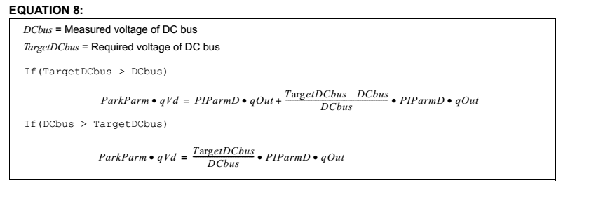
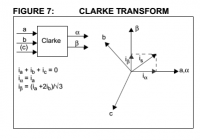
I am referring to the application note attached. I am bit confused with the Clarke Transform the statement from the document page no 8 is
"The first coordinate transform, called the Clarke Transform, moves a three-axis, two-dimensional coordinate system, referenced to the stator, onto a
two-axis system, keeping the same reference (see Figure 7, where ia, ib and ic are the individual phase currents)."
Q1. How it is concluded it is two-dimensional coordinate system? I was assuming since it is having 3 currents it should be 3 dimensional.
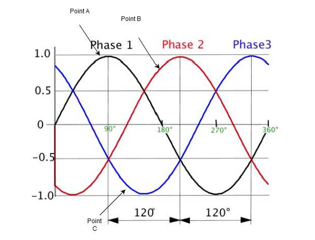
Q2. I have created one 3 phase system
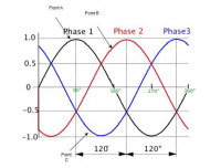
Assume points A, B,C of some magnitude let us say MagA, MagB, MagC.
where exactly they lie on the a,b,c axis. I mean to say i want to represent on the a,b,c axis.
Q3. And from the above diagram do the phase currents only have magnitude or do they have angle as well. For example for point A what is its angle? Please help.
"The first coordinate transform, called the Clarke Transform, moves a three-axis, two-dimensional coordinate system, referenced to the stator, onto a
two-axis system, keeping the same reference (see Figure 7, where ia, ib and ic are the individual phase currents)."
Q1. How it is concluded it is two-dimensional coordinate system? I was assuming since it is having 3 currents it should be 3 dimensional.
Q2. I have created one 3 phase system
Assume points A, B,C of some magnitude let us say MagA, MagB, MagC.

where exactly they lie on the a,b,c axis. I mean to say i want to represent on the a,b,c axis.
Q3. And from the above diagram do the phase currents only have magnitude or do they have angle as well. For example for point A what is its angle? Please help.