Continue to Site

Welcome to EDAboard.com

Welcome to our site! EDAboard.com is an international Electronics Discussion Forum focused on EDA software, circuits, schematics, books, theory, papers, asic, pld, 8051, DSP, Network, RF, Analog Design, PCB, Service Manuals... and a whole lot more! To participate you need to register. Registration is free. Click here to register now.

Sensor Input Protection

Status
Not open for further replies.

Murugesh_89

Full Member level 5
Joined
Nov 23, 2012
Messages
266
Helped
7
Reputation
12
Reaction score
6
Trophy points
1,298
Location
India
Activity points
3,267
Hi,

I am using a NPN type and PNP type inductive proximity and optical sensors in my project.

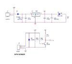
Sensor protection.jpg

The sensor connections will be given at the customer end. Even after documentation and legend in PCB, I am afraid if the customers giving the wrong connection. Say example: Power of sensor to signal in PCB likewise...

I want to ensure even if they wrongly connect it should not harm the control board.

Is there any way to achieve this?
 

Hi,

Use different connectors.
Don't make yourself responsible for other's mistakes.

The shown circuits are not very critical.
Maybe you could protect the optocoupler with a diode against reverse voltage.

Klaus

What's the use of optocouplers when both sides reference to the same GND?
Or are these the optical sensors?
 

Those are opto couplers PC817.

If the sensor is burst/malfunctioning then i dont want to have the impact to the micro controller. Hence i optically isolated the micro controller from the external circuitry.

Maybe you could protect the optocoupler with a diode against reverse voltage.
How should i connect the diode?
 

Hi,

PC817: You didn´t optically isolate them, because both sides have the same GND.
The same level of protection can be made cheaper without optocouplers. A simple bjt, or a current limiting circuit. The OPTO is useless.

***

Diode:
* either in series with the current.
* or inverse parallel to the optocoupler LED

Klaus
 
Hi,

I just given the schematic as per your suggestion..

Sensor BJT.jpg

Is this correct?
 

Hi,

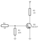
NPN.png
This ensures, that the microcontroller only sees voltage levels from 0V ... VCC.

Klaus
 

Hello Murugesh_89,
I suspect you have D2 in circuit to prevent accidental reverse polarity connection from your PSU?
If so, you need to place your 12V rail onto the cathode side if D2. Otherwise it will only be protecting the 7805 voltage regulator.
Regards,
Relayer
 

Status
Not open for further replies.

Part and Inventory Search

Welcome to EDABoard.com

Sponsor

Back
Top