gdylp2004
Member level 5
Hi guys,
I know feedback is a common problem being asked here but my key question is with Galvanic Isolation.
Consider attempting to sense an o/p voltage of a Buck converter that I've built: https://www.edaboard.com/threads/233047/, with the following deta
Output (o/p) voltage: ~28V DC
o/p voltage error: (+/- 2V typical)
Desired o/p voltage: 28V +/- 0.05V MAX
Ok with galvanic in mind, I wish to try optocoupler. After an extensive search, I realised that most isolated feedback circuit consists of 3 main modules which are:
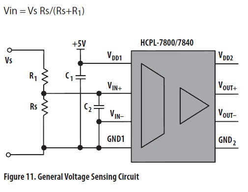
But to reduce complexity for such circuit, instead of 3 modules, I would like to try using only an optocoupler. I've browsed the Avago optocoupler selection guide and had found that the HCPL-7520 could be the one that suits best for me after reading this application note: Application Note - AN 1357; Overview of High Performance Analog Optocouplers (119 KB).
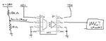
This is the schematic I saw and it resembles something which is very close to my idea.
I've selected HCPL-7520 instead of HCPL-7800 is because of its single-ended o/p that could be directly connected to the MCT w/o the need for any amplifier. Hence in this configuration, I've eliminated both the i/p and o/p amplifier.
I've drawn a circuit which shows my intention and would like to hear some comments if it would work or not. Please see attached and all comments or advise are welcomed.
The 10 and 10kΩ resistors are selected such that Vin lingers around in the range of 200mV or less so that the corresponding o/p is guaranteed accurate and linear (as recommended by the vendor). VDD1 & 2 are 5V, which will be powered by a linear reg which I've not drawn into my circuit. Lets put that aside first.
Datasheet for HCPL-7520: https://www.farnell.com/datasheets/1266244.pdf
I know feedback is a common problem being asked here but my key question is with Galvanic Isolation.
Consider attempting to sense an o/p voltage of a Buck converter that I've built: https://www.edaboard.com/threads/233047/, with the following deta
Output (o/p) voltage: ~28V DC
o/p voltage error: (+/- 2V typical)
Desired o/p voltage: 28V +/- 0.05V MAX
Ok with galvanic in mind, I wish to try optocoupler. After an extensive search, I realised that most isolated feedback circuit consists of 3 main modules which are:
- Sense amplifier where o/p of buck and a referenced value is given as input of the amp
- Isolator (optocoupler for this case)
- o/p amp to amplify the isolated signal for the MCT
But to reduce complexity for such circuit, instead of 3 modules, I would like to try using only an optocoupler. I've browsed the Avago optocoupler selection guide and had found that the HCPL-7520 could be the one that suits best for me after reading this application note: Application Note - AN 1357; Overview of High Performance Analog Optocouplers (119 KB).
This is the schematic I saw and it resembles something which is very close to my idea.
I've selected HCPL-7520 instead of HCPL-7800 is because of its single-ended o/p that could be directly connected to the MCT w/o the need for any amplifier. Hence in this configuration, I've eliminated both the i/p and o/p amplifier.
I've drawn a circuit which shows my intention and would like to hear some comments if it would work or not. Please see attached and all comments or advise are welcomed.
The 10 and 10kΩ resistors are selected such that Vin lingers around in the range of 200mV or less so that the corresponding o/p is guaranteed accurate and linear (as recommended by the vendor). VDD1 & 2 are 5V, which will be powered by a linear reg which I've not drawn into my circuit. Lets put that aside first.
Datasheet for HCPL-7520: https://www.farnell.com/datasheets/1266244.pdf