Continue to Site

Welcome to EDAboard.com

Welcome to our site! EDAboard.com is an international Electronics Discussion Forum focused on EDA software, circuits, schematics, books, theory, papers, asic, pld, 8051, DSP, Network, RF, Analog Design, PCB, Service Manuals... and a whole lot more! To participate you need to register. Registration is free. Click here to register now.

Sensing current flow through part(s) of the circuit?

Status
Not open for further replies.

jumper2high

Full Member level 3
Joined
May 24, 2009
Messages
178
Helped
20
Reputation
40
Reaction score
10
Trophy points
1,298
Location
Serbia
Activity points
2,579
hcpl-7510 schematic

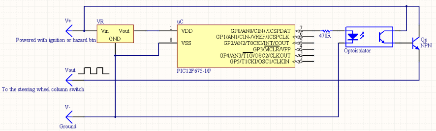
I am building an electronic (PIC controlled) timer for my car turn indicators (blinkers). The problem is, unlike some more modern cars, mine had an old timed relay that was 'before' anything else, and it only had three pins - two for it's power and one output. So, it was Relay -> Switch Behind Wheel -> Bulbs. The relay would only work when there is a load on it (it would only tick when the bulbs are connected).

The new one uses a transistor to create the timed signal, which means there is absolutely NO aural indication of the blinkers being on. For this, I would need to test whether the current IS flowing through the power transistor, and if it is - put some output onto a small speaker.

Because the relay was always powered, the MCU will also always be powered (when the key is inserted), so I can't have it just buzzing all the time. I need to sense when it's actually running (ie: when the switch lever is moved out of the neutral position).

My original idea was a simple shunt resistor, but I wasn't sure how would the 12V voltage on the transistor work with the 5V maximum of the MCU's ADC or Comparator.


N.B. The room for this circuit is quite limited, I need to use a minimal amount of components, and SMD isn't an option.
 

hcpl-7510 circuit

Try hall sensor for the current sensing
 

ina138 pic

Or an ACS712, it's not that difficult to solder ;)
Or you could use a 0.01 Ohm resistor and a rail-to-rail opamp.
 

pic adc current sensing

Thanks for the answers guys.
The thing is, I need to squeeze the whole thing in a relay box that is a cube with 1inch sides, and I'm not in the mood to custom-make a PCB since the cost of making it would pretty much defy the purpose.

So, I'm making it using the pre-drilled protoboard - which will fit the DIP8 MCU, DIP6 optocoupler, the voltage regulator switching transistor and a resistor or two.

Unfortunately, the use of the protoboard means I can't really do SMD. I've soldered SMD ICs and other stuff before, making a simple NE555 dual LED flasher just for fun - it wasn't too big of a deal. :)


Another issue is parts availability. I'm in Serbia, and Serbia isn't very popular when it comes to getting components easily. It took me three weeks and six phone calls to get a simple PIC18F4550 some time ago :| So, even though the hall sensor looks like a really neat thing, I most likely can't use it because I'll wait forever until it's shipped here :D
 

HI

You can use INA138/168 from TI as a current to voltage converter and sample the volatge using the PIC ADC

Depend on current flow you can use a small enough resistor for current sampling

All the best

Bobi
 

Hi Jumper2high,

I dont know your exact circuit configuration, but maybe HCPL-7510 can help. It is true DIP8 packaged current sensor. The output is single ended, so you can put in to ADC of uC/PIC. Output of 7510 is also 5V, input can be 12V no problem.
 

Do you really need to sense the current flowing through the bulbs? Or you need to check whether the light bulbs aren't burnt out? In case your aim is to control the bulbs /and the whole power elements of the relay/ - it's not obligatory to measure the current directly at all. I can offer you a method,which consists of 1-2 resistors and MCU with at least one ADC. You mentioned that the relay is powered all the time /3-pin relay,many of the modern cars are using the same type relays/,but there's no need to be generating all the time when is without load.

1.If your aim is to know only whether that the relay is loaded /turn_on signal switched on/,put a small resistor 10k from the output pin of the relay to a digital input pin of the MCU /taking care of signal conditioning of course/. Second resistor 4,7k in parallel with C-E / D-S if MOSFET/ of the power transistor.At power-up MCU shall not start to generate immediately,but rather staying in stand_by mode and checking the input signal I described above. If signal is "high" - do nothing,stay in stand_by and check signal periodically. If signal becomes "low" - this means that the load is connected /turn_on signal switched on/, start to generate. A safety issue demands the cycle of the relay to begin with "ON"-state /not pause/. That way a minimal time is lost from switching on the turn_on signal to actually bulbs get lit. In the way you are thinking of doing this /permanently generating/ ,it's not guaranteed. So ,after the "ON"-state of the relay, in the pause ,continue checking of the input signal . If "low" - continue to generate,else /"high"/ - stop generate. If you've detected "low"signal and have started to generate,but in "ON"-state the signal stays "low" - this is indicating failure of the power transistor or adjacent elements.

2.If you want to check the bulbs' health - use the same schematic with two resistors,but lower 4,7k to 680 - 1k/0,5W.The input pin of the MCU must be analog with ADC. How it works - in the pause,immediately after power transistors is turned off,measure with ADC /10-bit/ the voltage drop across the bulbs.The bulbs' filaments at this moment are still hot, with ~3ohms resistance /for appr. 50W for a side/.Need just to check the voltage drop,if a burnt bulb/s is/are present ,the drop will increase.Do some experiment and you'll find the proper reference voltage.
 

Teodor, the first solution you mentioned sounds like it may work. While describing it, though, you made one assumption (relay) which isn't present in my circuit. I am using a simple NPN transistor to turn the LEDs (not bulbs) on and off.

Here's a schematic of how it looks:
92_1248622115.png


If you're able to, could you try and draw a schematic of what you had in mind to accomplish the behavior you described in the first paragraph - detecting when the transistor is loaded.
 

Hi,

Have read your thread about the original timer and the new timer, perhaps I've missed some point but - in both cases why not simply put a cheap piezo sounder on the 12v line to the bulbs so it sounds in time with the bulbs coming on - you could use a twin sounder with different notes for left or right.
 

Wp100, there are two reasons for that:


1. The cheap buzzer sounds cheap :D With the MCU, I could choose the frequency and length of the tone which means I could make it much better sounding.

2. I would need to rip out half of the steering column to reach the wires that lead out of the switch - something I am trying to avoid. The idea was to make a 'bolt on' solution, just take out the old one and put in the new one, without any 'fiddly' stuff.
 

Hi,

A simple way of getting feed back for the pic, put a reed relay or minature relay with its coil across 0v and the transistors output - this will then operate its contacts in time with the pulses / bulbs on, so letting your pic generate the 'cool' sound.

Just in case - would always pull Mclre up to VCC in a 'noisy' envrioment
 

MCLR has been disabled in config - so I don't have to waste space/time pulling it up to Vdd.

If I put a relay across the transistor output, I'll always click, since the MCU is powered when ever the key is in the ignition. The switch in the steering wheel only connects Vout to the lights.
 

I am using a simple NPN transistor to turn the LEDs (not bulbs) on and off.
Sorry,but I've missed this,I was assuming that you are using bulbs. The second method I described is not plausible in this case.

Take a look at the schematics.The first one senses current ,the second one utilizes the first method I described.
 
Teodor, thank you very much. The solution you suggested gave me an idea of how to make it work! :D


By the way, where are you from - if it's not a secret :p
 

No,it's not a secret :D .Actually we are neighbours - I'm from Bulgaria :D .
 

Hehe, I thought you were from somewhere around here, since West-European folks spell your name as 'Theodor' (with an h) :D


Once again, thanks for the help, man.
 

Status
Not open for further replies.

Similar threads

Part and Inventory Search

Welcome to EDABoard.com

Sponsor

Back
Top